Adding a Simulation Model to a Component Definition
Contents
- Specifying the Requirement of a Simulation Model
- Adding the Simulation Model Link
- Adding Component-Level Simulation Parameters
- Defining the Component from a Simulation Perspective
- Model
- Parameters
- Pin Mapping
- Verifying the Model in the Released Component
- Auto-Generation of a CmpLib
- Full Support for Digital SimCode Models
Parent article: Releasing a Component Definition to a Vault
On the design side, each design component released to an Altium Vault is specified using a source Component Definition. A component definition is simply just that – a definition of a particular design component. A definition that ties together the required models and parameters for that component in a clean and ordered fashion.
In terms of its representation in the various design domains, a vault-based component doesn't contain the domain models themselves, but rather links to these models. Along with the typical Schematic Symbol and PCB 2D/3D component model – released to the vault as Schematic Symbol and PCB Component Items respectively – you can also link to a required simulation model, released to the vault as a Simulation Model Item.
This document takes a look at adding a simulation model to a component definition within a Component Library (*.CmpLib), including component-level simulation parameter definition and configuration of pin mapping.
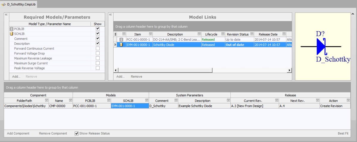
Component Library with a definition for a Schottky Diode. The Schematic Symbol and PCB Component Item Revisions are already linked. All it needs now is for the Simulation Model Item (which has already been released to the vault) to be added!
Specifying the Requirement of a Simulation Model
Firstly, the simulation model type needs to be added to the Required Models/Parameters list within the Component Library. This simply adds a field for that model type to the component's definition. To do this, click the Add control at the bottom of the Required Models/Parameters region, and choose the SIM entry from the menu.
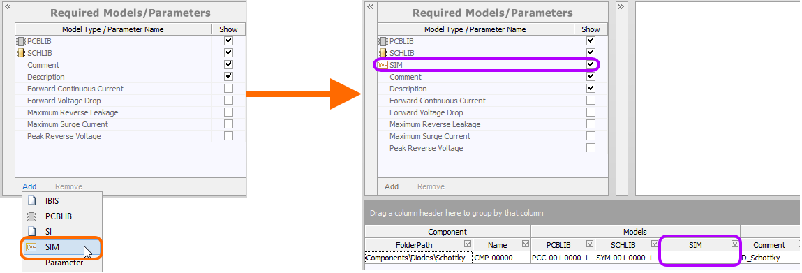
Specify the SIM model type to be made available for use in component definitions.
Adding the Simulation Model Link
With the SIM model type added to the list of required models, you can now proceed to add the actual link to the required (and previously released) Simulation Model Item. Simply click on the Add control at the bottom of the Model Links region and choose the SIM entry from the menu. The Choose Models dialog will appear, from where you can browse within the targeted vault and select the required model. The link will be added to the region and a preview of the SimModel file displayed in the preview window to the right.
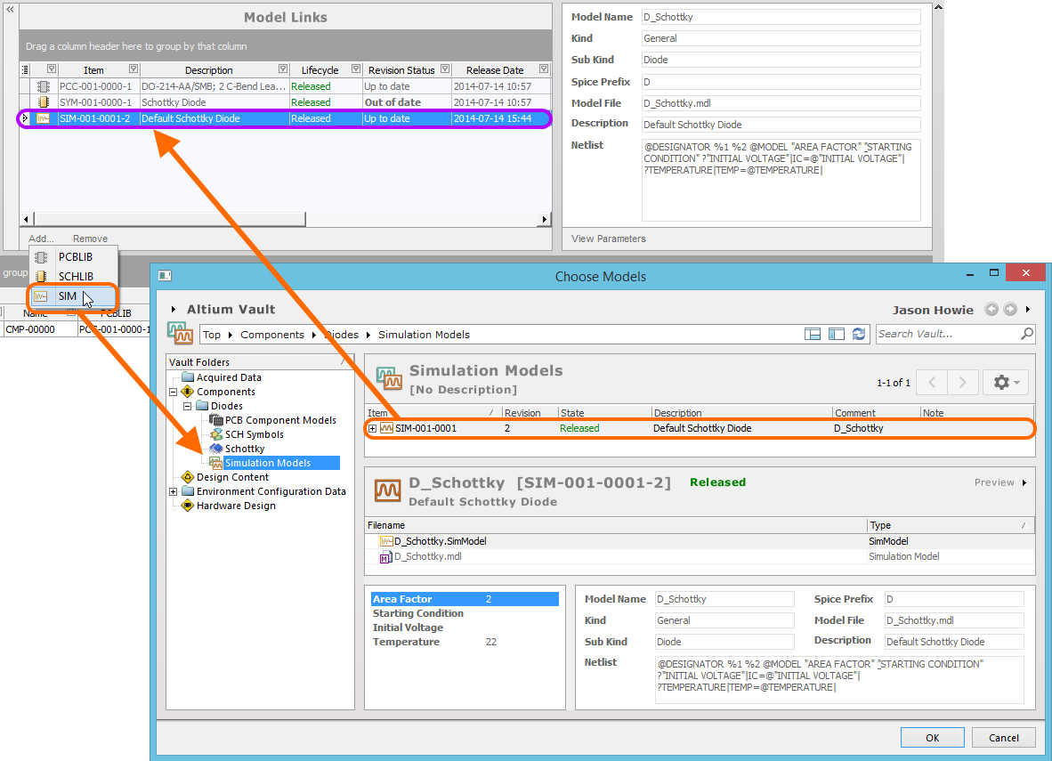
Add a link to the specific revision of a Simulation Model Item that will represent the component in the simulation domain.
Any number of SIM model links may be added, including links to different revisions of the same model Item. Each link is to a specific named-revision of a Simulation Model Item (e.g. SIM-001-0001-1, for revision 1 of Simulation Model Item SIM-001-0001). Using the Show in Explorer command on the right-click menu for a selected model link will quickly access the Vaults panel, with the chosen Simulation Model Item Revision in focus.
Adding Component-Level Simulation Parameters
When using a simulation model for a component in a design, parameters specific to that model can be specified at two different levels:
- Model-Level Parameter –specified as part of the simulation model definition itself (in the SimModel file), and released with that definition into a revision of the linked Simulation Model Item.
- Component-Level Parameter – specified as part of the component definition (here in the CmpLib), and released with that definition into a revision of the linked Component Item.
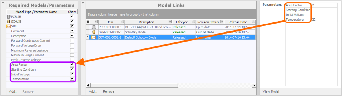
Parameters are added at the component-level in the Required Models/Parameters region of the Component Library document. It is important to note that the naming of parameters must be the same as those parameters defined at the model-level. To see the model-level parameters, and therefore which parameters can be added at the component-level (and their names!), select the SIM model link and click the View Parameters control, at the bottom of the preview window.
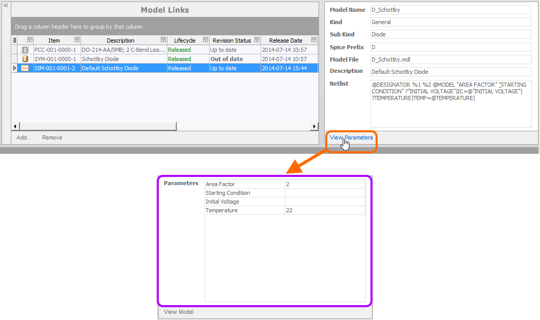
View the model-level parameters for a Simulation Model Item, to see which parameters can be added at the component-level - and how they are named!
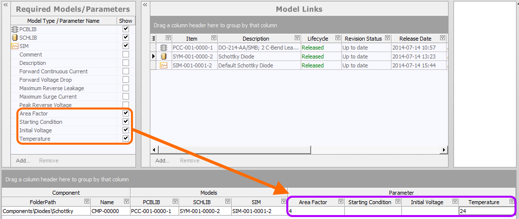
Armed with the available model-level parameters, you can now proceed to add any of those same parameters at the component-level – to be available to any component definition in the library. To do so, simply click the Add control at the bottom of the Required Models/Parameters region. A new parameter entry will be added to the list. Change the name as required – remembering to match exactly the name of the corresponding model-level parameter.
Add sim-related parameters at the component-level.
Defining the Component from a Simulation Perspective
With the model link added and any component-level simulation parameters defined as required, you can proceed to add/define the simulation 'portion' of the component's definition.
Model
Clicking on the SIM field for the definition will provide access to a dedicated model link pop-up window. This presents a grid of all existing simulation model links, complete with all data columns. Simply select the model link required to be used to represent that component in the simulation domain, and either press Enter or double-click to assign that model.
Specify the SIM model to be used for the component.
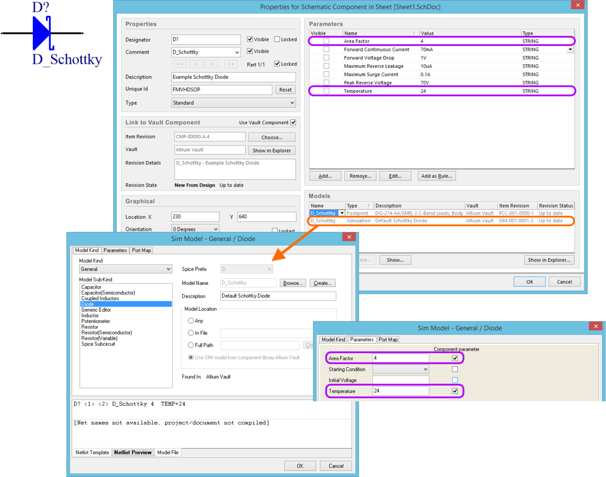
Parameters
Locate the fields corresponding to the component-level simulation parameters that you have entered in the Required Models/Parameters region of the document. There is one field per parameter. Simply enter values for these parameters as required.
Specify values for component-level simulation parameters.
Pin Mapping
Once the link to the required SIM model has been chosen, you need to ensure that the pins of the component – when represented in the schematic domain – are correctly mapped to the pins of the simulation model. This is performed in the Pin Mapping dialog, accessed by right-clicking on the SIM model entry and choosing Edit Pin Mapping from the context menu. For each schematic pin, simply use the available drop-down to change the associated Model Pin entry accordingly. If the device is multi-part, be sure to check the mapping for each part.
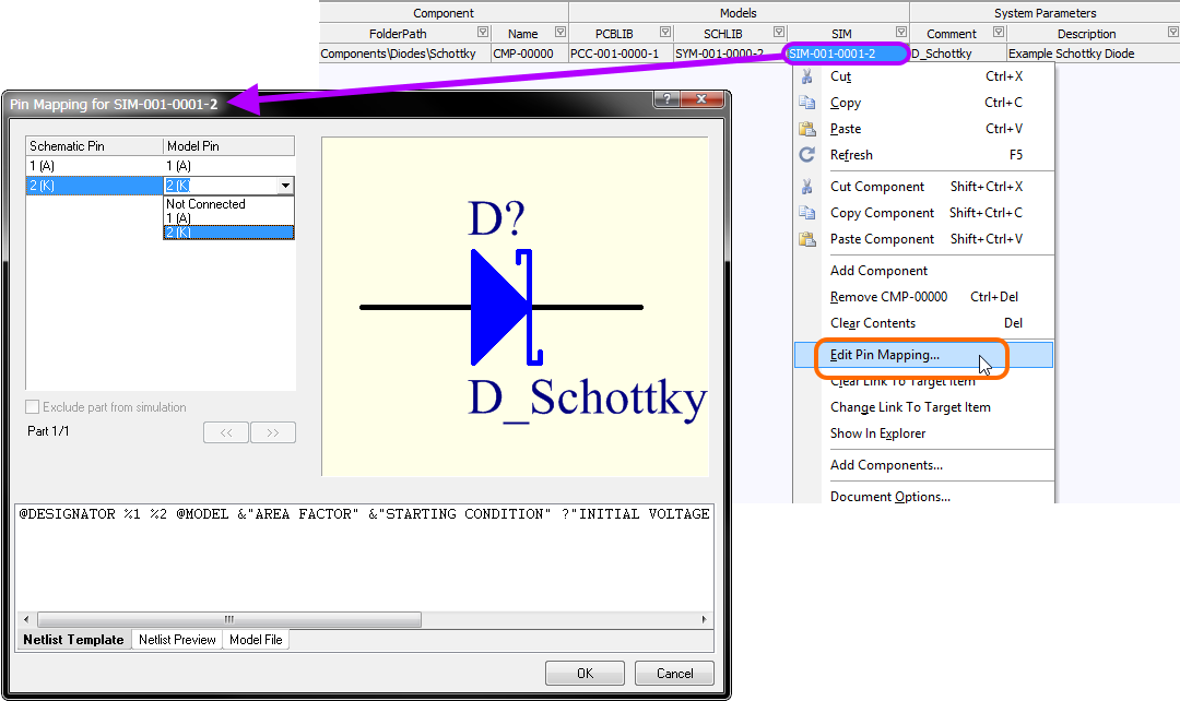
Ensuring correct schematic pin-to-model pin mapping.
Verifying the Model in the Released Component
Once the component definition has been released to the target Altium Vault, the resulting Component Item can be browsed in the Vaults panel. Direct access can be made after release by right-clicking on the component definition and choosing Show in Explorer from the context menu.

View the released component directly in the target vault, courtesy of the Vaults panel. Note the linked Simulation Model Item (altium-simulation-model) and the component-
level simulation parameters.
The simulation model link and associated component-level simulation parameters can also be verified when an instance of the Component Item-Revision is placed on a schematic sheet.
Verifying the simulation model link and component-level simulation parameters after placing an instance of a particular revision of the Component Item.
Auto-Generation of a CmpLib
Related article: CmpLib Generation from Active Schematic Library
One particularly useful tool in the context of Component Libraries is the ability to generate these automatically from source Schematic Libraries:
- Either from the active Schematic Library, using the Tools » Generate Component Library command.
- From multiple Schematic Libraries stored in a nominated source folder, using the batch-style Release Manager (File » Release Manager).
This tool takes the manual labor and potential for error out of the equation when creating the source component definitions from which the vault-based Component Items are generated.
The effort you have already spent in building a collection of simulation-ready components in you source Schematic Libraries is not ignored or discarded and you are not required to duplicate that effort! The tool uses the information for each original source schematic component in such a library to essentially fill-in the required fields of the component definition:
- The Items created from the release of schematic symbol, simulation model definition and linked PCB 2D/3D Component model are used as the model links for the definition.
- The Symbol Reference and Description parameter values are used as the values for the Comment and Description parameters in the definition.
- All user parameters defined for the schematic component – including those simulation-related parameters added as component-level parameters – are added as required parameters for the definition.
Full Support for Digital SimCode Models
When using a vault-based component that references a Simulation Model Item featuring a SimCode definition (in a *.scb file), that scb file (released with the SimModel file to the vault) is used for subsequently run simulations. In the generated simulation netlist (*.nsx file), the model reference will contain the full path to the scb file, cached locally from the vault. For example:
.MODEL 74LS90 xsimcode(file="C:\ProgramData\Altium\AD {A586F887-1E00-4F36-9EC8-61C78B91FA73}\VaultsFileCache\0072B38F-E431-40BB-B462-FD262DB9CDAB\9A7AB3DA-D4A5-43B3-9C88-33A56E86A0BF\Released\LS.SCB" func=ls90)