Releasing a Component Definition to a Vault
Contents
- The Component Definition
- The Component Library
- File-less Editing
- Working with the CmpLib Editor
- Specifying the Target Vault
- Specifying Required Models & Parameters
- Model Links
- Adding Model Links
- Out of Date Models
- Controlling the Display of Columns
- Grouping Model Links
- Sorting
- Column-based Filtering
- Access to File-less Editing of Linked Models
- Defining Components
- Component Definition
- Addition of Multiple Components
- Grouping, Sorting and Filtering
- Presentation of Data
- Component Definition Editing
- Targeting an Existing Component Item
- Performing the Release
- Re-releasing the Component Definition
- Streamlined Re-release Through File-less Editing
- Releasing Multiple Component Library Files
Parent article: Vault-Based Components
Once all prerequisite domain models have been created and released into a vault, a design component can be defined and released. Components are formally modeled as file-based definitions that can be released into a vault for reuse in a design project. Revision-controlled and lifecycle-managed, a company can authorize the 'set' of components that can be formally used by their designers.
Once in the vault, a design component – or Vault-based Component – can be extended to include real-world physical component information, creating a component that spans, or rather unifies, the Design and Supply Chain arenas – a Unified Component.
This article focuses on bringing the required pieces together to define and release a Component Definition into a vault – the 'design view' of that component.
The Component Definition
The engineering, or design view of a component is, in essence, a container into which all information used to model that component in the design arena is stored. This includes links to all requisite domain models (schematic symbol, PCB 2D/3D component, Sim, SI, etc), as well as parametric information. What's more, this abstracted 'bucket'-type modeling is very scalable, should the component need to be represented in additional design domains in the future.

The design view of a component – a neatly packaged container for all information required to
represent that component across the various design domains.
But how to specify a component? Or, more precisely, how to determine the contents of that container? The answer, on the design-side, is to create a Component Definition.
A component definition is simply just that – a definition of a particular design component. A definition that ties together the required models and parameters for that component in a clean and ordered fashion. Each component definition on the design-side maps to an Item – a Component Item – in a target Altium Vault. Each release of the component definition stores the component data into a new revision of that Item.
The Component Library
In terms of storage, component definitions are created and managed within a dedicated Component Library file (*.CmpLib). A new file of this type can be created using the File » New » Library » Component Library command. A single Component Library file can be used to create (and therefore map to) one or more unique Component Items in a target vault, by entering one or more component definitions. Each component definition will have a common set of parameters and links to required domain models.
Create and manage design-side component definitions within a Component Library file.
File-less Editing
Main article: File-less Editing in an Altium Vault
With the arrival of File-Less Editing, the CmpLib editor becomes a true session editor, rather than a data source. So instead of being the definitive source for each component, which must be stored carefully on a hard drive, or backed-up under version control, it now becomes a streamlined tool with which to make changes to components, and re-release to new revisions of those components, without a physical file in sight. And this goes for inital component creation too - simply define the component and release, then discard the CmpLib file. With the component data released and stored securely in the vault, it becomes redundant.
Working with the CmpLib Editor
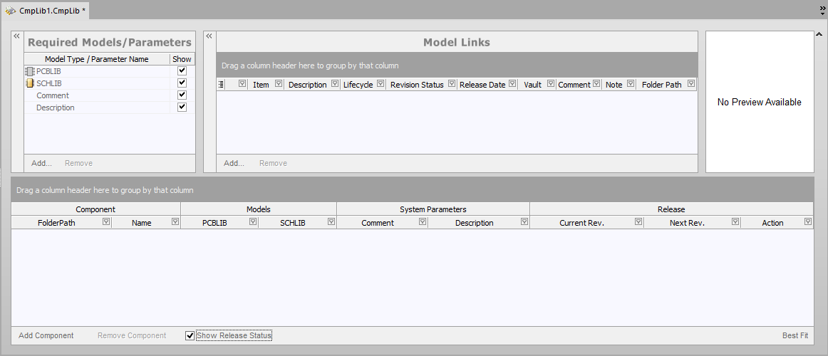
The following sections take a closer look at the various regions of the Component Library document, and how a component is defined within this document.
Specifying the Target Vault
Controls for specifying the target vault in which the Component Items, generated from the source component definitions, will be created – and also the lifecycle definition and revision naming schemes to be employed for those Items - are available in the Document Options dialog (Edit » Document Options).
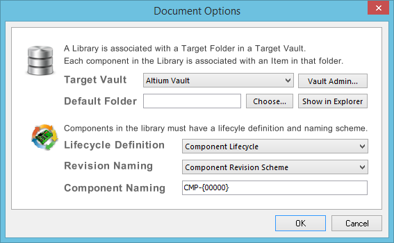
Vault settings are defined through the Document Options dialog.
Use the drop-down associated with the Target Vault field to choose from a list of Altium Vaults that your instance of the software is currently connected to, and that are enabled for use by the software. If you have not connected to a vault, or need to connect to a different vault, click the Vault Admin button to the right of the drop-down to access the Data Management – Vaults page of the Preferences dialog, from where you can make a connection to the required vault as necessary.
Use the Default Folder field to specify a default folder within the target vault in which to store the released Component Items. Do this by clicking the Choose button to access the Choose Folder dialog - a cut-down version of the Vaults panel, from where you can browse to and choose an existing folder in the vault, or create a new one on-the-fly. The entry here will be used by default for the FolderPath when adding a new component definition.
The Lifecycle Definition and Revision Naming fields are set to use a suitable default scheme in each case (Component Lifecycle and Component Revision Scheme respectively). Use the drop-down associated with each field to choose a different scheme, from any of the currently defined schemes available for the targeted vault.
The Component Naming field is used to define a default Item Naming Scheme for components released from the CmpLib file, ensuring a unique ID for each resulting Component Item in the vault. The entry here will be used as the template for automatically naming a newly-added component definition (in its associated Name field). The software will automatically assign the next available unique ID, based on that scheme, having scanned the entire vault and identifiers of existing Items.
Specifying Required Models & Parameters
The Required Models/Parameters region of the document is essentially the place where you define what type of domain models are required by the component definitions, as well as the place to craft a set of parametric data that will be applied to all component definitions.
- Models - at the most basic level, a design component used in board design requires representation in the schematic and PCB editing domains. It therefore needs schematic symbol and PCB 2D/3D Component models. These then are added as required models by default and cannot be removed. Use the Add and Remove controls for the region to add/remove other model types as required.
- Parameters - two default parameter entries exist –
CommentandDescription. These are system parameters. Any number of additional parameters may also be added as required. To do so, simply click the Add control at the bottom of the region, then choose the Parameter entry. A new parameter will be added to the list. Click inside the Parameter Name field to change the name as required. To remove a parameter, simply select it and click the Remove control. The system parameters cannot be removed.
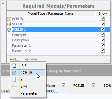
Define required models and parameters.
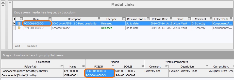
Model Links
The Model Links region of the document is where you add links to released domain models, for use in component definitions. Links to models of a particular type can only be added provided that model type has been added to the Required Models/Parameters region. The model links region can be thought of in terms of a 'bucket' of domain models that can be accessed by any component definition in the Component Library document. Assignment is simply a case of specifying which links are required for each definition.
The Model Links region, packed with functionality to streamline model link definition and assignment to the component definitions.
Adding Model Links
There are a couple of streamline ways in which to add model links to the region:
- Select multiple models for addition within a given vault folder. Either the latest revision of multiple different model items in that folder, or multiple different revisions of the same model item. Simply click the Add control beneath the Model Links region, then choose the models of the required type through the Choose Models dialog.
Dialog-based addition of multiple model links.
- Drag and drop models directly from the Vaults panel. You can drag one or more different models, one or more different revisions of the same model, or the entire folder of models (which will result in the latest revision of each model in that folder appearing in the Model Links region).
Add one, multiple, or an entire folder of models through drag and drop from the Vaults panel.
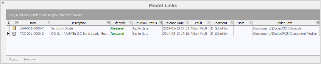
Any number of model links may be added, including links to different revisions of the same model. Each link is to a specific named-revision of a model (e.g. SYM-001-0000-2, for revision 2 of Schematic Symbol Item SYM-001-0000). Using the Show in Explorer command on the right-click menu for a selected model link will quickly access the Vaults panel, with the chosen model (and revision thereof) in focus.
Out of Date Models
The Revision Status field for a model link is used to indicate whether it is the latest revision of that particular model, or if there is a subsequent revision available for it. When the CmpLib Editor detects that a linked Model is not the latest Revision, this is flagged by the text Out of Date, shown in a bold font.
To update the link to use the latest revision of the model, simply right-click on the Revision Status entry and choose Update to Latest Revision from the menu. This action:
- Updates the model link to reference the latest revision,
- Updates any usage of that model in a component definition, to use the latest revision of that model.
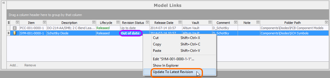
The CmpLib Editor details any model that is not at the latest revision, right-click to update them.
Controlling the Display of Columns
To enable or disable the display of a specific column, click the Column Control button ![]() and disable any columns you do not want to be visible.
and disable any columns you do not want to be visible.
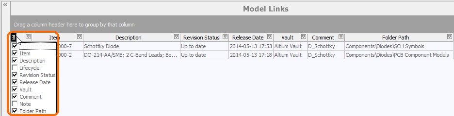
Hide or show model link data columns as required.
Alternatively, to hide a column, simply click and drag its header to a point in free space, until a large cross appears, then let go.
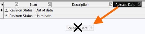
Drag a column header into free space to hide its display.
Grouping Model Links
Model links can be grouped based on any of the visible column headings. To do this, click and hold on a column header, then drag and drop it onto the text that says Drag a column header here to group by that column.
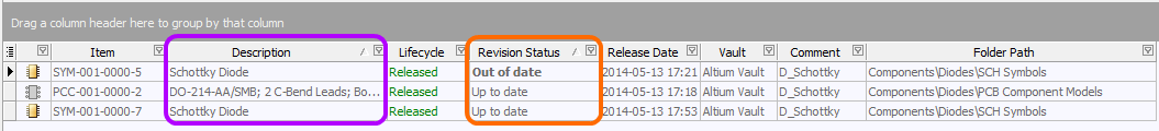
For example, the following image illustrates the model links being grouped by Revision Status. Doing so separates the model links into as many groups as there are different values in the grouping column - in this case two groups are created, for Revision Status: Out of date, and Revision Status: Up to date.
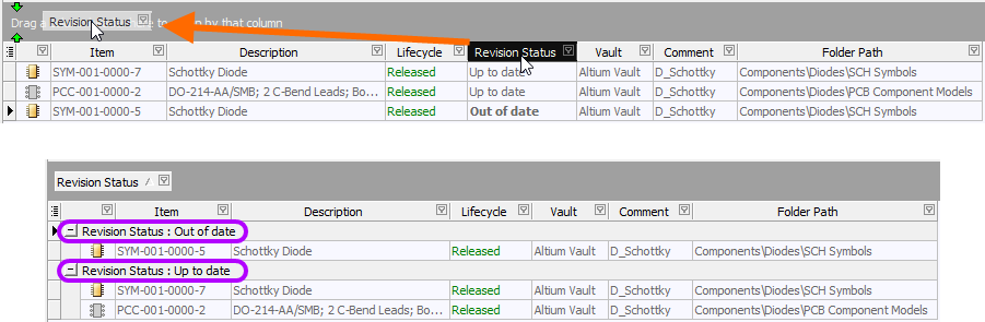
Grouping the model links based on the values in a column, in this case by Revision Status.
Sorting
Model links can be sorted by a specific column simply by clicking on that column's header. Click once to sort in ascending order (based on the content of that column). Click again to sort in descending order.
You can sort by multiple columns. With the model links already sorted by a specific column, simply Shift+click on another column to 'sub-sort' by the content of that column.
Example sorting, primarily by the Revision Status column, and secondarily by the Description column.
Column-based Filtering
Like an Excel spreadsheet, the model links can be further filtered by the contents of each column. To do this, click the small funnel (filter) icon, located at the right-hand side of a column header (![]() ). A menu will appear containing a checkbox for each value present in that column. Enable the required checkbox(es) to reduce the list to only include model links with that value.
). A menu will appear containing a checkbox for each value present in that column. Enable the required checkbox(es) to reduce the list to only include model links with that value.
Alternatively, for greater filtering control select (Custom..), which displays the Custom Filter dialog. Use this dialog to set up a custom filter to meet your requirements, by specifying which rows of information you want to show based on filter criteria you apply to the data column.
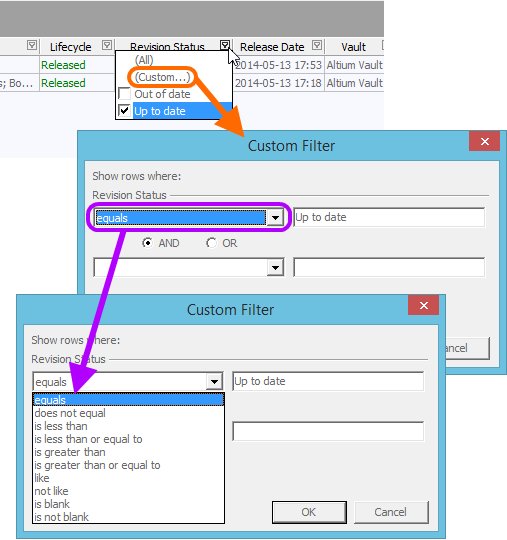
Choose to apply standard or customized column filtering.
When a column filter is applied, the filter icon is displayed in blue (![]() ), indicating that there is filtering applied based on that column. Filtering can be applied to multiple data columns. Each 'column filter' becomes an ANDed condition in the overall filter. A textual representation of the filtering currently in effect will be presented at the bottom of the region.
), indicating that there is filtering applied based on that column. Filtering can be applied to multiple data columns. Each 'column filter' becomes an ANDed condition in the overall filter. A textual representation of the filtering currently in effect will be presented at the bottom of the region.

An example of column filtering in action.
To further customize the current filter, click the Customize button, to the far right of the textual representation of the filter, to open the Filter Builder dialog. Use this dialog to create more sophisticated and complex filters as needed.
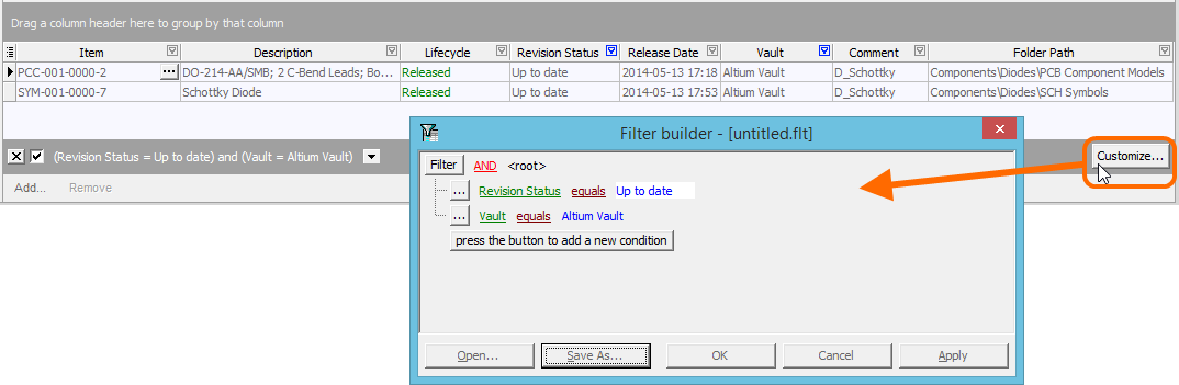
Use the Filter Builder to create more sophisticated filtering.
Access to File-less Editing of Linked Models
Should you need to edit a linked domain model that is used by a component definition in the CmpLib, this can be done most efficiently using the file-less editing paradigm:
- Right-click on the model entry in the Model Links region of the editor, and choose the Edit command from the context menu.
- The model will open in a temporary instance of its associated editor. Make changes as required to the model and save.
- Then release into the next revision of the parent item in the vault, using the File » Release to Vault command. The Create Revision dialog will appear, in which you can enter a different Comment and/or Description, or simply enter a note of the changes made in the Release Notes field.
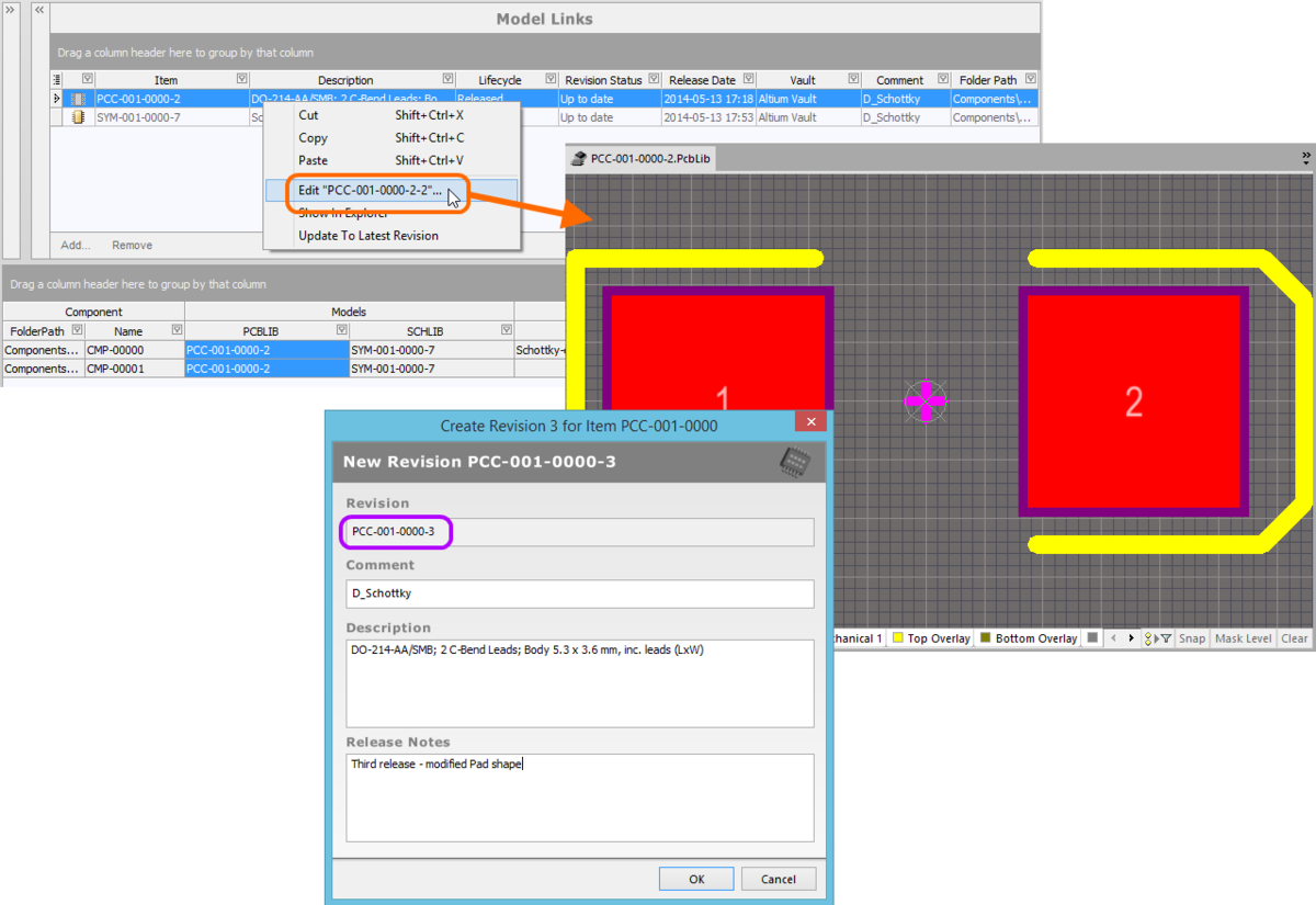
Edit and release a model directly from the Model Links region of the CmpLib Editor.
Clicking OK in the Create Revision dialog will effect the release. The temporary editor will close and you will be returned to the CmpLib Editor. The model link and any instance where that link has been assigned to defined components, will be automatically updated with this latest revision.
Model link and assignments are updated with the latest revision after the release process completes.
Defining Components
Once you have specified the set of parameters, and have your 'bucket' of model links at the ready, you can proceed with the 'meat' of the Component Library document – definition of the required component(s). This is performed in the lower region of the document.
Define your components in a logical and intuitive way, using the hierarchy-less component editor.
Component Definition
Each component definition appears as a single row entry containing the following information:
- Component: FolderPath - use this field to release the component to a specific folder in the target vault. For each newly added component to the grid, this field can be populated with a default location, if specified in the Default Folder field in the Document Options dialog (Edit » Document Options).
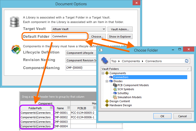
Specifying a default vault folder in which to release components.
Whether or not a default path is specified, you have full control over where in the target vault a component will be stored. To manually specify a target folder, click once inside the FolderPath field for a component to reveal the ![]() button, and click to access the Choose Folder dialog. Browse to, and choose an existing folder, or create a new one on-the-fly.
button, and click to access the Choose Folder dialog. Browse to, and choose an existing folder, or create a new one on-the-fly.
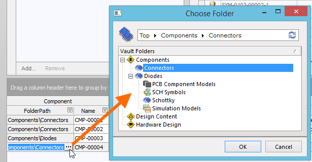
Manually specifying the release folder for a specific component.
- Component: Name – this field is used to determine the ID used for the released Component Item in the vault. For each newly added component to the grid, this field is populated in accordance with a default naming scheme, specified in the Component Naming field in the Document Options dialog. The software will automatically assign the next available unique ID, based on that scheme, having scanned the entire vault and identifiers of existing Items.
A default Item naming scheme – CMP-{00000} – is provided, but you can of course create your own scheme, simply by typing it within the field, ensuring that the variable portion is enclosed in curly braces (e.g. CMP-001-{0000}). Alternatively, you can override the auto-assigned ID for a component, simply by entering the ID required directly in the Name field for a definition. You always have full control and final say over how the Items are identified!
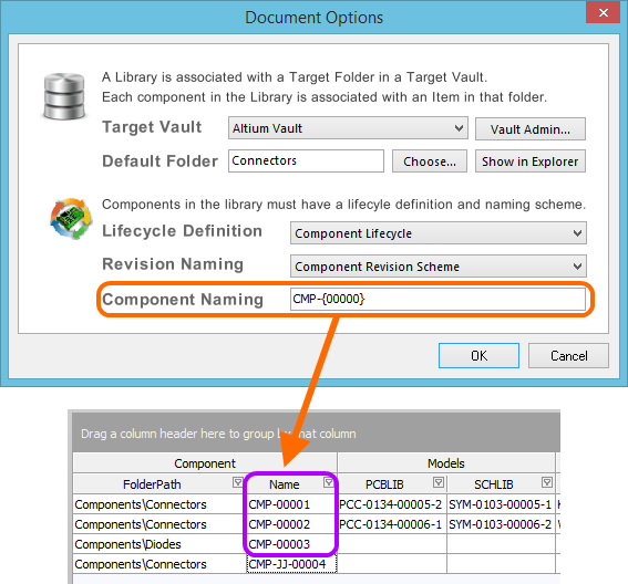
Components are named automatically, according to the specified Component Naming for the document
(highlighted above). This can be overriden by manually entering a unique ID as required.
-
Models – these fields correspond to the entries in the Required Models/Parameters region of the document. There is one field per required model that is added. There will always be at least two models associated to a component, corresponding to the default schematic symbol and PCB 2D/3D Component models. Each filed is used to specify which of the linked models (in the Model Links region) is to be used for the component. Assigning model links to components can be performed in the following ways:
-
Drag and drop a model link into the relevant column of an existing component definition.
-
Assign a model to an existing component using drag and drop from the Model Links region to the corresponding model column for that component.
- Drag and drop a model link into free space to add a new component definition that uses that model.
Assign a model and add a new component on-the-fly, using drag and drop from the Model Links region.
- Drag and drop a model directly from the Vaults panel into the component definition region. A new component definition using that model will be added. In addition, if that model does not exist in the Model Links region, an entry will be added for it.
Assign a model and add a new component on-the-fly, using drag and drop from the Vaults panel. The model link will be added to the Model Links region, if it does not exist already.
- Use the drop-down field for a model column to access a dedicated model link pop-up window. This presents a grid of all existing model links applicable to the model type being assigned, complete with all data columns. This can be a real time saver for finding and assigning a model, where the number of component definitions hamper drag and drop techniques, or the top section of the CmpLib Editor - housing the Model Links region - is collapsed.
Click and drag the ![]() control at the bottom-right of the window to resize the pop-up. Click the column control button
control at the bottom-right of the window to resize the pop-up. Click the column control button ![]() and disable any columns you do not want to be visible. Columns can be reordered by dragging a column header.
and disable any columns you do not want to be visible. Columns can be reordered by dragging a column header.
Use the pop-up's search field to quickly locate the model required. Dynamic highlighting based on data across any column is applied as you start to type characters. Select the model link required and either press Enter or double-click to assign that model.
Use the dedicated model link selection pop-up to search, locate and assign the model required.
-
System Parameters – these are the
CommentandDescriptionparameters. Enter values for these as required. TheCommentparameter can be particularly useful as a means of tagging the component with a more humanly-readable name, such as the name used for that component in other component management methodologies. This name is also available and indexed when searching within the vault and will provide a good means to locate specific components beyond having to remember their Item ID! -
Parameters – these fields correspond to the additional parameters that you have entered in the Required Models/Parameters region of the document. There is one field per additional parameter. The left-to-right ordering of the parameters in a component definition corresponds to their top-to-bottom ordering in the Required Models/Parameters region. Simply enter values for parameters as required.
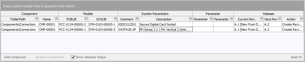
- Release: Current Rev. – this non-editable field reflects the current (most recent/latest) revision of the Component Item in the target vault.
- Release: Next Rev. – this non-editable field reflects the next revision of the Component Item that will be created when the component definition is next released, in accordance with the chosen revision naming scheme.
- Release: Action – this field shows the action that will be taken by the release manager for this particular component definition, as part of the release process. For a component definition that has not yet been released, this entry will display
Create Item. For a definition that has already been released, this entry will displayCreate Revision.
Addition of Multiple Components
The CmpLib Editor facilitates addition of multiple new components in one hit. Simply right-click and choose the Add Components command. Then, in the Add Components dialog that is presented, enter the number of components you wish to add. In concert with the grids multi-cell editing support, and copy/paste features, you can quickly build an impressive array of component definitions in quick time.
Add multiple new component definitions in two quick steps.
Grouping, Sorting and Filtering
Components can be grouped, sorted and filtered using controls and techniques in the same way as the Model Links region. Refer back to the relevant sections on how to do this, earlier in this document.
An example of customized grouping and filtering in the component definitions region of the editor.
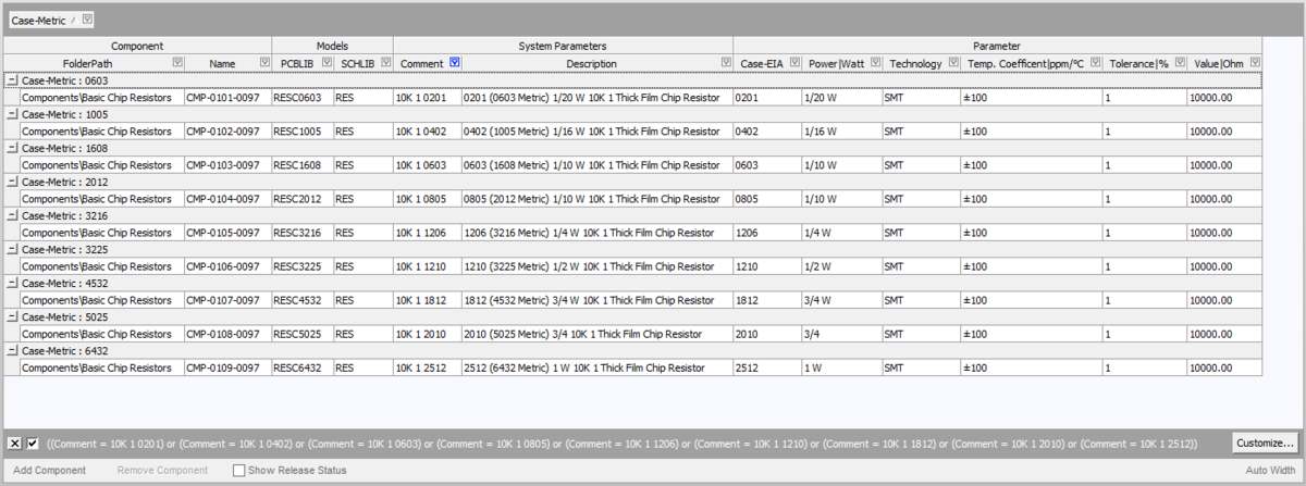
Presentation of Data
Depending on the type of components being defined, there could be a sizeable number of regular (user-defined) parameters, all of which, when added to the other columns of data, can create a veritable tangle of partially-legible content. Addressing this, a couple of display modes are available for the component definitions region. Switch between modes using the control at the bottom-right of the region.
- Best Fit - in this mode, each column of data is sized to display all data within it, in accordance with the largest data entry and adding a little padding for good measure. Since each column is sized to display its data, the columns can collectively extend beyond the currently viewable area. In support of this a horizontal scrollbar is provided to allow ease of reading.
Example use of the Best Fit display mode.
- Auto Width - in this mode, the software will attempt to display all data columns within the viewable area of the grid, stretching or condensing as needed. This mode works fine when there are not so many data columns, but legibility can suffer when a great number of columns are present.
Example use of the Auto Width display mode.
Component Definition Editing
Depending on the components you are creating, a single Component Library file may end up containing a sizable number of component definitions. In some cases, these definitions may differ only slightly and many may require similar model or parametric information. The document supports various editing features that enable you to quickly effect changes to one or more component definitions.
- Multi-cell editing is implemented for models and parameters. Multiple data cells within a column can be selected for operation using standard Ctrl+click, Shift+click and click&drag keyboard functionality. To assign a model to multiple components, select the range of cells, then click the dropdown select to display the model link pop-up window, as shown below. Double-click on the required model in the pop-up, this model will then be assigned in all selected model cells.

Select multiple components, then select a model for them all in a single action.
For parameters, simply select the required cells within the same column, then enter the required value for the focused cell and either click away or press Enter. All cells in the selection will receive that same value.
- You can copy and paste data between selected data cells using the corresponding commands available on the right-click menu.
- You can clear the contents of selected data cells using the Delete key (or the Clear Contents command on the right-click menu).
- You can copy, cut, and paste selected model links, required models/parameters, or component definitions, using Ctrl+Shift+C, Ctrl+Shift+X and Ctrl+Shift+V respectively.
- You can remove selected component definitions from the file completely, using the Remove button below the component definition grid, the Remove command from the right-click menu, or the Ctrl+Del shortcut.
- You can refresh the content of the grid using the Refresh command on the right-click menu (or by clicking the button on the Component Library Standard toolbar).
- You can copy selected data cells to the Windows clipboard, for manipulation in an external spreadsheet application. Component definition information in an external spreadsheet can also be pasted back into the component definitions region of a Component Library document.
Targeting an Existing Component Item
For the most part, you would typically leave the creation of the Component Items in the target vault to be part of the release process. You simply add your component definitions, assign Item IDs and away you go – Item creation 'on-the-fly' as it were. However, you may have created (or want to create) Component Items directly in the vault, then link to these existing Items. Not a problem.
The right-click menu associated with a component definition contains a couple of commands to support linking a definition to a manually-created Component Item:
- Change Link To Target Item – use this command to access the Choose Target Item dialog, which you can use to browse for and select the required Component Item in the target vault.
- Clear Link To Target Item – use this command to clear the link to an existing Item in the vault. The Release-related fields of the component definition will revert back ready to create a new Item.
Performing the Release
Having defined the component definition(s) as required in the Component Library file, the release of the file can now proceed. The release process is simply the act of generating a new revision of each targeted Item. The release process is performed from within the Release Manager dialog.
The Release Manager dialog is accessed using the File » Release To <TargetVaultName> command. This is a modified version of the full Release Manager dialog, the difference being that in this context it is used to release the single, active library document, rather than batch-release multiple libraries in a nominated source folder.
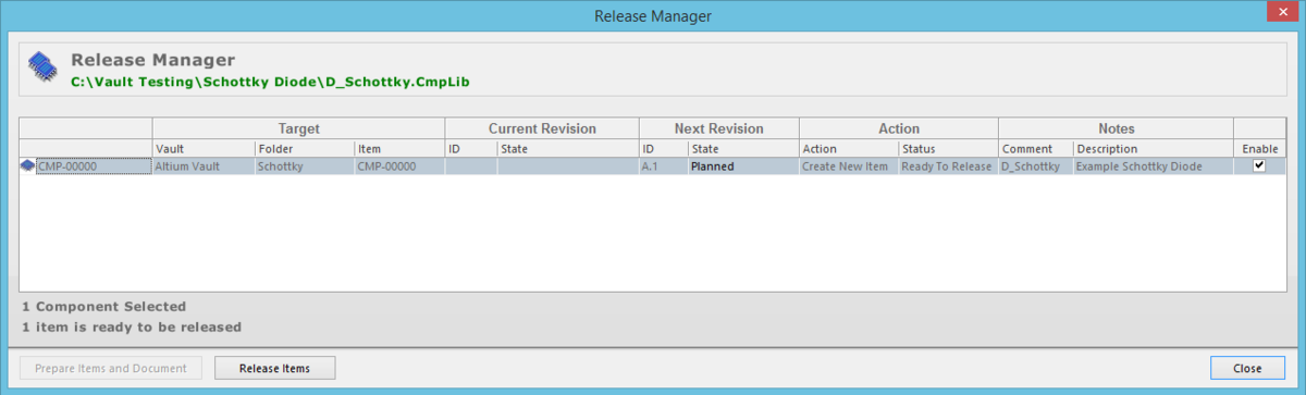
The document-level Release Manager streamlines the process of releasing the active CmpLib.
Analysis and file preparation are automatically performed. The release process simply becomes a 3-step affair:
- Exclude any components you do not want to be released, by unchecking their associated Enable option.
- Enter any Notes as required (a Comment and/or Description) for each component being released. By default, these are automatically populated with the values for the system parameters (Comment and Description).
- Click the Release Items button.
The Confirm Release dialog will appear, allowing you to review the release actions either at a summary level, or at a more detailed level. If the release actions are correct, proceed to release by pressing OK.
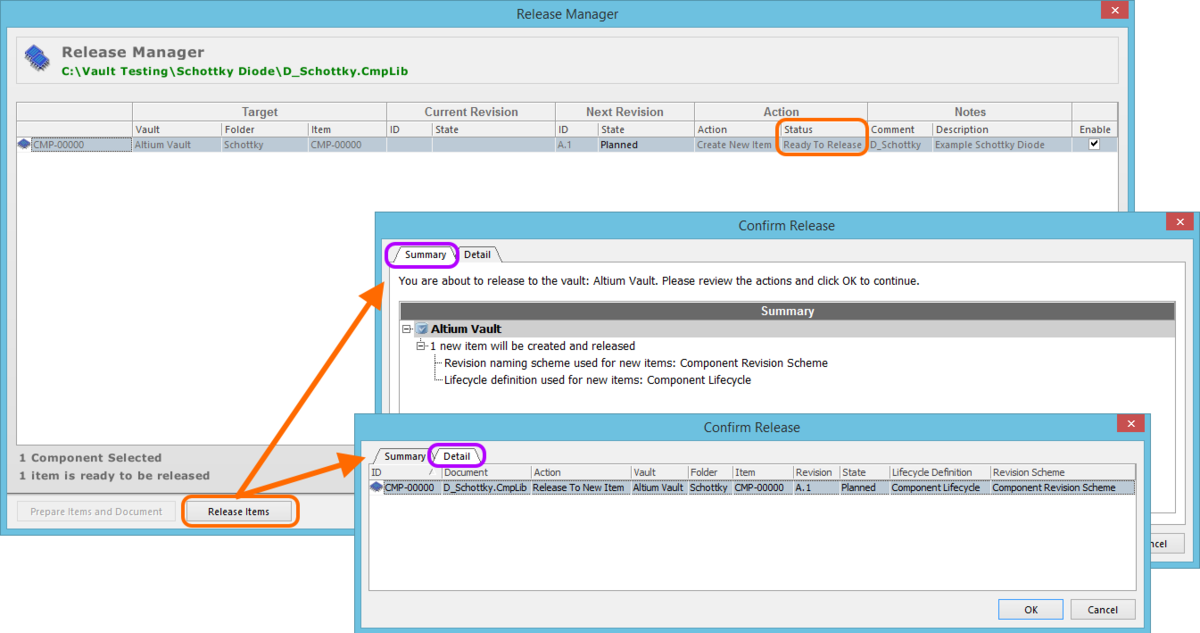
Review and confirm the actions that will be taken by the release process.
Back in the Release Manager dialog, the Action-Status field will display Release Running..., changing to Release Succeeded on completion of the process – provided the release was successful.
Where a definition is being released for the first time, a new Component Item will be created in the target folder within the vault, with the specified ID, and linked back to that definition.
Once released, you can browse the component(s) directly in the vault using the Vaults panel. Jump directly to a Component Item in the vault from the Component Library, by right-clicking on its component definition and choosing the Show in Explorer command.
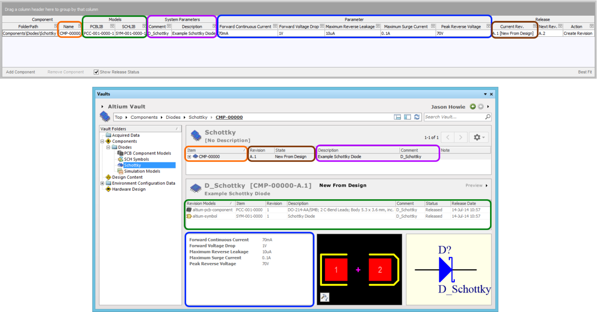
A released Component Item viewed directly from within the target vault, courtesy of the Vaults panel.
The released data stored in the vault consists of links to the released domain models and the parametric information.
The Component Library file will be updated to reflect the release. The Current Rev. entry will show the revision and current lifecycle state of the new release. The Next Rev. field will automatically be filled with the incremented revision – the next revision of the Item that will automatically be created and used to store data if the linked source component definition is released again.
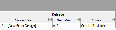
The current and potential next revision of the Component Item is reflected back in
the Component Library file.
Re-releasing the Component Definition
With the source Component Library document linked to the vault and folder therein, re-releasing a component definition (or definitions) in that library – to take into account any modifications – is a straightforward process:
- Make changes to the component definition(s) as required.
- Save the library file.
- Use the File » Release To <TargetVaultName> command.
The source library document and linked target folder and Items therein will be analyzed and the Release Manager dialog will present updated link and status information and ready the library and its constituent definition(s) for possible re-release. The action for a component definition that is being re-released now appears as To New Revision.
Only component definitions that have been modified in some way will be enabled ready for release. In this case, analysis and file preparation will again be performed automatically, meaning all you need to do to proceed with the re-release is click the Release Items button.
Streamlined Re-release Through File-less Editing
Main article: File-less Editing in an Altium Vault
File-less editing frees you of the shackles of separate version-controlled source data. You can simply edit a supported Item type using a temporary editor loaded with the latest source direct from the vault itself. And once editing is complete, the entity is re-released into a subsequent planned revision of its parent Item, and the temporary editor closed. There are no files on your hard drive, no questioning whether you are working with the correct or latest source, and no having to maintain separate version control software. The Altium Vault handles it all, with the same great integrity you've come to expect, and in a manner that greatly expedites changes to your data.
Releasing Multiple Component Library Files
Main article: Batch Releasing to a Vault with the Release Manager
When migrating components from existing component management methodologies to the next-generation vault-based component model, releasing Component Libraries each containing a single component definition can be a tedious task – especially since release of a single Component Library file requires that file to be open and active in Altium Designer. This is also the case if you have made changes affecting component definitions across an array of source Component Libraries, that need to be re-released into a new revision of each target Component Item.
To facilitate the release of multiple libraries to a target vault simultaneously, Altium Designer provides a Release Manager (File » Release Manager). Unlike the streamlined version of this dialog – which is concerned with the active document only – this is the full release 'console'. Use it to batch-release component definitions stored across multiple Component Libraries in a nominated source folder location.
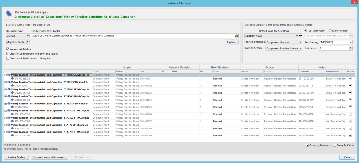
Release component definitions, stored in one or more source Component Libraries, using the Release Manager.