Output

Function
The Output panel provides detailed information with respect to all stages of the Process Flow when compiling, synthesizing, building and ultimately downloading the chosen FPGA design to the physical device.
The information displayed in the panel depends on the activity being performed. The following sections consider each of the areas of the general Process Flow, used when programming a physical device.
Compile
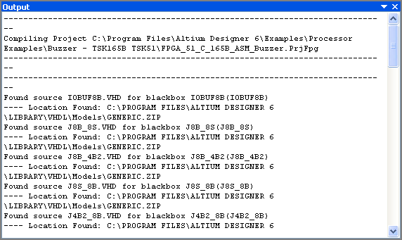
When compiling the source documents for the chosen FPGA project, the Output panel will display any information with respect to the compilation of any linked embedded software projects. Any notices, warnings, errors or fatal errors will be also listed as messages in the Messages panel, along with the result of the compile.
Synthesize
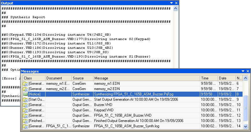
When synthesizing, the Output panel will display full details of the synthesis, including core generation and synthesis of design/device specific blocks used in the FPGA design (e.g. RAM).
All synthesis information is also displayed in the Messages panel.
Build
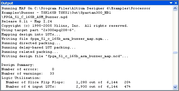
When this stage of the Process Flow is run, invoking the Vendor Place & Route tools, the panel is populated with very detailed information concerning each sub-stage in the build process. There are five such stages:
- Translate Design - uses the top-level EDIF netlist and synthesized model files, obtained from the synthesis stage of the Process Flow to create a file in Native Generic Database format (NGD)
- Map Design To FPGA - maps the design to FPGA primitives.
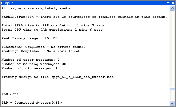
- Place and Route - takes the low-level description of the design (from the mapping stage) and works out how to place the required logic inside the FPGA. Once arranged, the required interconnections are routed.
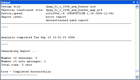
- Timing Analysis - performs a timing analysis of the design, in accordance with any timing constraints that have been defined. If there are no specified constraints, default enumeration will be used.
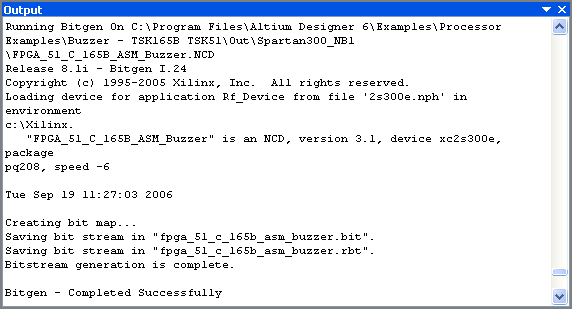
- Make Bit File - generates the programming file that is required for downloading the design to the physical device.
In each case, the Messages panel will display entries showing the start and completion of each stage, as well as any specific notices, warnings and errors.
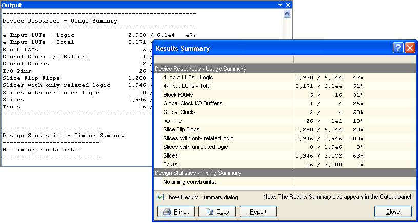
At the end of the build stage, the Output panel will list the following information:
- Device Resources - Usage Summary
- Design Statistics - Timing Summary
Both of these summaries are also displayed in the dedicated Results Summary dialog.
Program FPGA

When downloading the design to the physical device, the Output panel displays information relating to the download, including the time taken to download and the speed of download. This information is replicated in the Messages panel.
Right-click Menu
The right-click pop-up menu for the panel provides the following commands:
- Select All - select all text currently displayed in the panel
- Copy - copy the selected text to the Windows clipboard
- Clear - clear all text currently displayed in the panel.
Notes
- The keyboard shortcuts Up Arrow, Left Arrow, Down Arrow and Right Arrow can be used to navigate through the content of the panel. Use the CTRL + HOME and CTRL + END shortcuts to jump to the first and last entry respectively.
- The Results Summary dialog is, by default set to appear automatically. This can be enabled/disabled using the Show results summary dialog at End of run option on the FPGA - Devices View page of the Preferences dialog (DXP » Preferences).
- The panel will also display information when recompiling embedded software projects or synthesizing VHDL designs, outside of the Process Flow of the Devices view.