Releasing a Design with the PCB Release View
Contents
Parent article: Board Design Release
Once a design is considered ready for flight into the wider world, it needs to be released – a process that can often be underestimated.
As part of Altium’s wider Design Data Management solution, Altium Designer provides powerful, high-integrity board design release management. The release process is automated, enabling you to release your design projects or, more specifically, defined configurations of those projects, without the risks associated with manual release procedures.
Facilitating this process is Altium Designer's PCB Process Manager, the graphical interface to which, is the PCB Release view. The latter presents a high-level 'Dashboard' that operates in two modes: Design Mode and Release Mode.
Access to the PCB Release view is made using the View » PCB Release View command, or by clicking the ![]() button on an editor's Standard toolbar.
button on an editor's Standard toolbar.
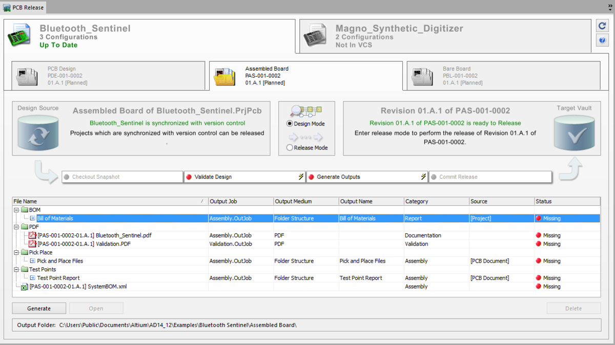
The PCB Release view is the graphical interface used to perform the board design release process.
View Breakdown
Before exploring the use of the PCB Release view in either Design Mode or Release Mode, it is a good idea, at this point, to take a closer look at the elements that constitute the view – a summarizing breakdown if you will.
Open Projects
The topmost region of the view presents a distinct tab for each PCB design project you currently have open within Altium Designer – as reflected in the Projects panel. Each tab displays the following information:
- The PCB project name
- The number of configurations currently defined for the project
- Version control status information. For a PCB project under version control, the entry will reflect the state between your local sandbox copy and the fileset stored in the repository (Design Repository). This includes states such as
Up To Date,Unsaved Changes,Local ChangesandFiles Missing From VCS. For a PCB project that is not part of version control, this entry will remain static and readNot In VCS.
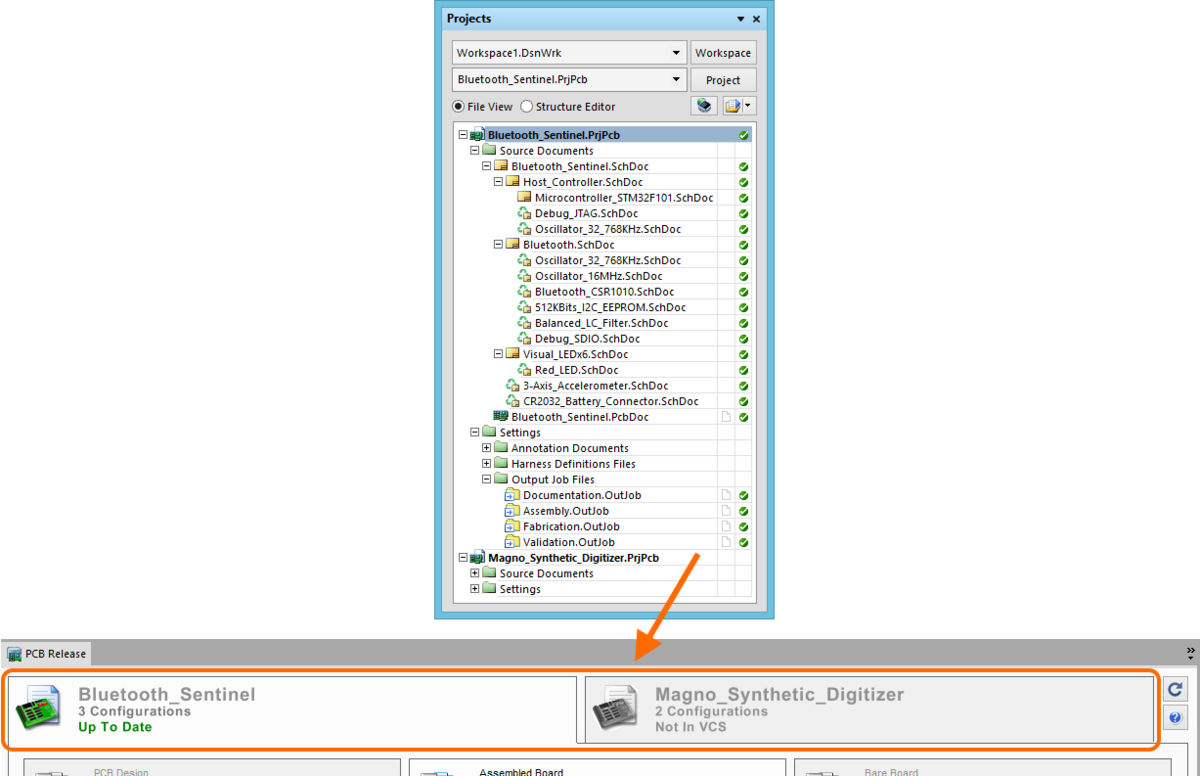
An example of two projects open and presented in the PCB Release view.
Project Configurations
Main article: PCB Project Configurations
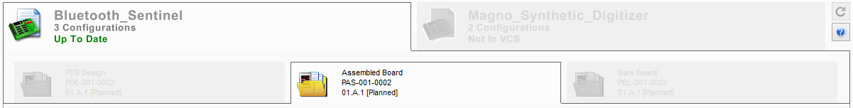
Clicking on a project-level tab in the view will present all configurations currently defined for that project, as a set of sub-tabs.
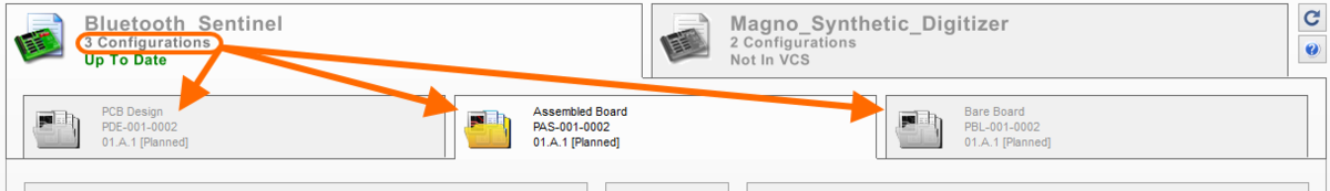
An example showing three configurations defined for the chosen project, Bluetooth_Sentinel.PrjPcb.
Each tab displays the following information, as defined in the Configuration Manager dialog (Project » Configuration Manager):
- The name of the configuration
- The ID of the Item in the target Altium Vault, to which the configuration is currently mapped.
- The current revision of that Item (and its lifecycle state).
Process Flow
Each configuration has an associated Process Flow. In its entirety, this flow represents the board design release process – getting the design from the Design Repository, processing the chosen configuration of it, and committing generated release data into the referenced Item Revision in the nominated Altium Vault.
This region of the configuration sub-tab is essentially divided into the following areas:
- The Design Source region, on the left side, presents status information for the active design project in the view.
- The Target Vault region, on the right side, presents status information pertaining to the targeted Item Revision that the chosen configuration maps to.
- Between these two regions are controls for switching between Design Mode and Release Mode.
- Directly below is the graphical representation of the actual Process Flow – the board design release process itself.
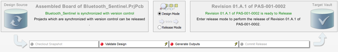
An example of the process flow (in Design Mode) for a chosen configuration.
The overall flow consists of four distinct stages as follows:
- Checkout Snapshot – a snapshot of the data, including dependencies, is checked out from the applicable Design Repository (where applicable).
- Validate Design – all defined validation output generators, defined in an Output Job file assigned to the configuration being released, are run. This includes running any of:
- Differences Report – using the comparator to determine if the source and PCB design documents are correctly in-sync.
- Electrical Rules Check – checking the electrical/drafting validity of the captured source design.
- Design Rules Check – checking the validity of the PCB document in relation to specified board-level design constraints.
- Footprint Comparison Report – comparing footprints on the board against their source library to ensure they are up-to-date, and matched.
- Environment Configuration Compliance Check – checking that only data items permitted through the environment configuration available for use by your assigned role (if applicable), are being used. This check can also ensure that all design items are sourced from an Altium Vault.
- Generate Outputs – all other defined outputs in the assigned Output Job file(s) are run. These are the outputs that drive the release of the target Item, the instructions from which the physical Item will be produced to exist as a tangible product which can be bought and sold.
- Commit Release – pushing the generated outputs and validated design document snapshot into the defined new revision (planned revision) of the target Item, stored in the nominated Altium Vault.
What you can actually do in the flow depends on the mode you are currently in – Design Mode or Release Mode.
File Generation
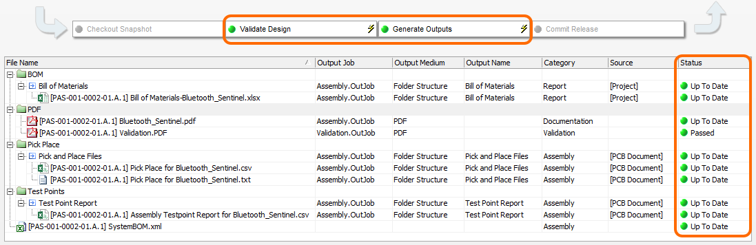
The final region in the view is a listing of all outputs defined across the Output Job files assigned to the chosen configuration being released. The storage structure reflects output paths defined for the relevant output containers in the associated Output Job file(s). In addition, a dedicated entry for the System BOM will be appended to the bottom of the list, named using the format [ItemID-RevisionID] SystemBOM.xml.
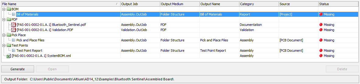
Example list of outputs to be generated for a chosen configuration.
For each output the following information is presented:
- File Name – the name of the generated output, prefixed with the Item ID and Revision ID (e.g.
[PAS-001-0002-01.A.1] Validation.PDF). For an output associated to theFolder Structureoutput container, this field initially displays the name for the output (identical to the Output Name field). When the output is generated, this field expands to show the actual file name. - Output Job – the Output Job file in which the associated output generator for this output is defined.
- Output Medium – the name of the associated output container into which the output will be generated (e.g.
PDFs,Files,Videos). - Output Name – the name specified for the associated output generator in the applicable Output Job file.
- Category – the specific output category within the Output Job file, to which the output is associated.
- Source – the source from which the output is generated, as defined in the Data Source field for the associated output generator, in the Output Job file. Note that if multiple output generators are associated with the generated file (e.g. for a PDF document), and they have differing data sources, this field will be blank.
-
Status – the current state of the output. The following table lists the possible states:
State
Description

Output has not yet been generated/does not exist.
Output has been generated, but changes have since happened on the design side, making the validity of this data no longer current.
The output is currently in the process of being generated.
The output is validation-based and has generated a report free of any errors. For an ERC report, there are either no errors, or the level of those errors falls within the specified maximum tolerated error level for that report.
The output (excluding validation-based outputs) has generated successfully.
The output has not generated successfully. For a validation-based output (DRC, ERC, Differences, Footprint Comparison, Configuration Compliancy) this means errors exist within the source design documents that are causing certain check(s) to fail. For a standard output, the output could not be generated successfully. Perhaps Fatal Errors exist when performing a pre-generation compile, or something is amiss in the configuration of the associated output generator, in the Output Job file.
Generate, Open and Delete buttons below the list (and corresponding commands on the right-click menu) allow actions to be performed on selected outputs when in Design Mode.
Using the View in Design Mode
The Design Mode of the PCB Release view is used for controlling and managing the Board-Level design process. Here you can run validations and generate outputs as needed, and in any order, 'testing the waters' as it were to ensure all is as it should be, prior to initiating the actual release of the intended configuration.
In this mode, you are free to move between defined configurations in any of the currently open projects. The aim, in this mode, is to essentially concentrate on a particular configuration of the project you want to release, and ensure that everything is ready-to-go. When it is, you'll be able to switch the view into its Release Mode, and perform the actual release.
Getting Access to Release Mode
Looking at the following image, there are essentially three areas which need to be 'Green Stated' before Release Mode becomes accessible.

In Design Mode, three key areas need to return a successful status before access to the Release Mode is granted.
In summary, these are:
- The status display on the parent project tab.
- The Design Source region of the configuration sub-tab.
- The Target Vault region of the configuration sub-tab.
The first two of these are basically the same indicator and relate to use of a version-controlled Design Repository. To be in a 'green and ready' state, the local working copy of the design project (your sandbox) must be synchronized with the master fileset in the repository. If, for example, you have added new design files or modified existing ones, then the design will no longer be in-sync. You need to add new file(s) or commit changes as required, to get back to a fully synchronized state.
To aid in resolving any issue in this area, if the state is Files Missing From VCS, Out Of Date, or Local Changes, hyperlinks will become available in both regions, providing access to a dialog listing the offending files and enabling you to commit or update as required to obtain a fully synchronized state.
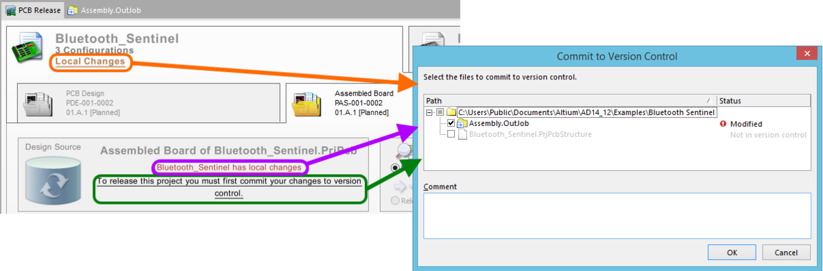
Click a hyperlink to access the relevant dialog used to facilitate synchronization between the Design Repository and local copy.
With the target vault, you need to ensure that you firstly have a vault connected, and that Items have been created within. You must then ensure that the configuration of the project you wish to release actually points to a defined Item within that vault – referencing its unique ID. If the configuration is not mapped to a valid Item in the vault, the configuration tab and Target Vault region will reflect this. Hyperlinks will become available providing access to the Configuration Manager dialog, from where you can specify which Item in the vault the configuration is to map to.
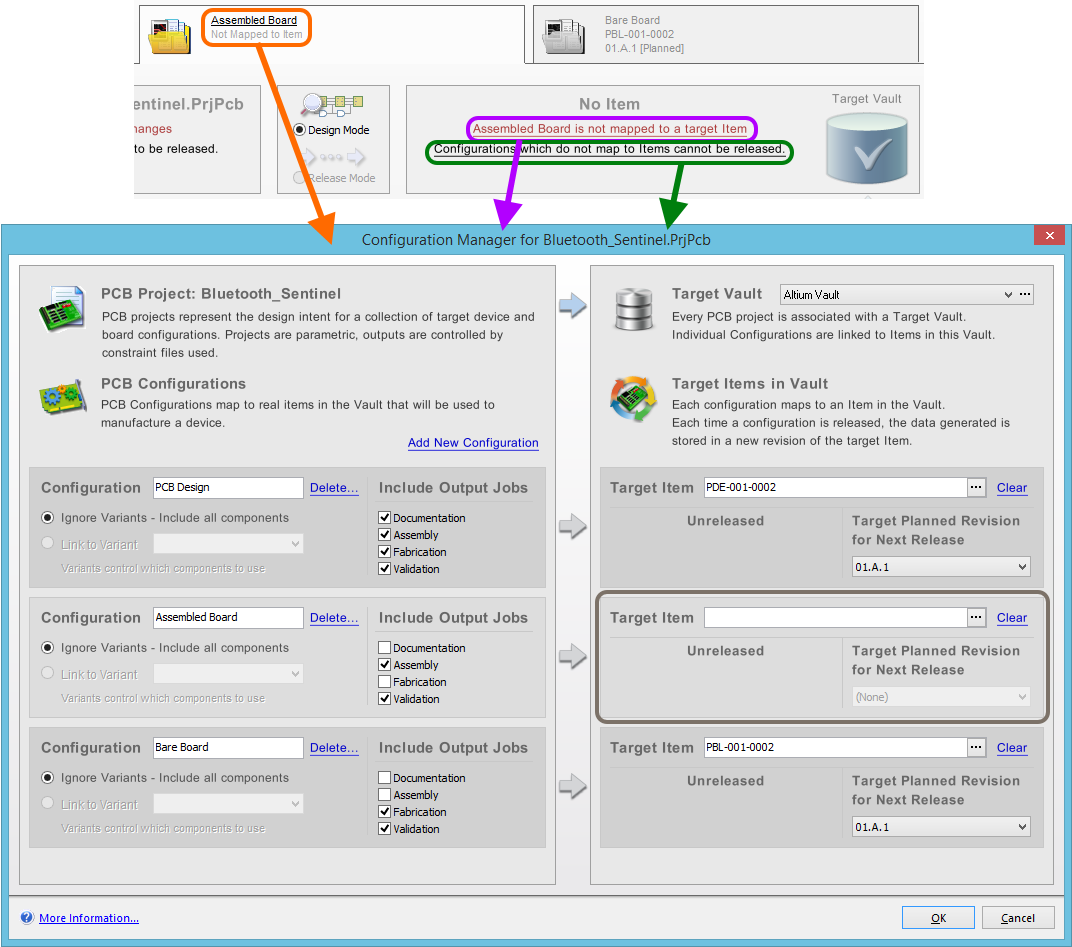
If a target Item is not defined for the configuration, the PCB Release view will show no item is mapped. Click a hyperlink to access the Configuration Manager dialog, and map the configuration to a valid Item in the target vault.
Depending on the lifecycle definition employed for an Item a revision of that Item can, post-release, be set to various lifecycle stages – New From Design, In Prototype, In Production, to name a few. However, to access Release Mode and subsequently release a project configuration, the Item revision MUST be in the Planned state. If this is not the case, the Target Vault region will flag this. Click a hyperlink in this region (or the configuration tab region) to access the associated Item view for the Item. From here, you can create a new planned revision of the Item as required.
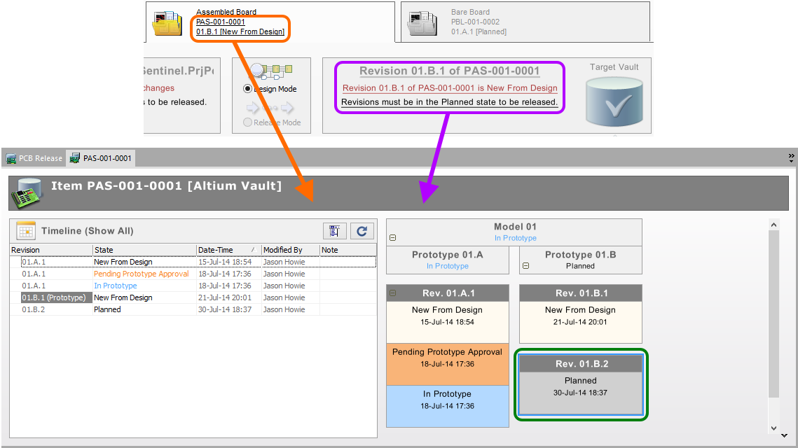
If the configuration is not mapped to a planned revision of the target Item in the vault, the PCB Release view will reflect this. Click a hyperlink to access the Item view, from where a new revision can be created.
Validation and Output Generation
Related article: Validation Output Reports
In Design Mode, the Process Flow appears as shown in the following image.

Example appearance of the Process Flow in Design Mode when all is set up and configured correctly.
Notice that only stages 2 and 3 of the flow are active and enabled in this mode – Validate Design and Generate Outputs. These two stages are the 'meat' of the flow and their successful running is crucial to the board design release process. If either of these stages fails, the release fails – simple as that. So within Design Mode, access to these stages gives you arguably the most valuable pre-release checking aid possible.
To run all outputs associated to a particular stage, simply click the button for that stage, or the ![]() icon at the right of the button:
icon at the right of the button:
- Validate Design – to run all validation-based outputs defined in Output Job file(s) assigned to the chosen configuration.
- Generate Outputs – to run all other outputs defined in assigned Output Job file(s), in addition to the System BOM.
As a stage is being executed, the text on the button will change to reflect which output is currently being generated, and how many outputs have been generated so far out of the total to be run.
![]()
The current state of output generation for a stage is also reflected in the button for that stage.
The state in each output's Status field will reflect when that output is running and then the result once generation is complete. If all outputs are generated successfully – validations all Passed and other outputs are Up To Date – then success is guaranteed with respect to these stages when running the flow in Release Mode.
Success in Design Mode - an example design validates fine and all outputs execute successfully - means guaranteed success also when running these stages in Release Mode.
Offering further flexibility, Design Mode enables you to generate output on an individual basis. Simply select the particular output you wish to generate (a validation report, a standard output, or the System BOM) and click the Generate button at the bottom left of the file listing. Once generated, you have the ability to view that document (click Open or double-click the entry) and subsequently delete it (click Delete) as required.

Generate and view output at the individual document level.
Using the View in Release Mode
The Release Mode of the PCB Release view is for initiating releases of PCB Project configurations. This is where the high-integrity board release process is performed, taking the specified configuration of the design project and processing it to obtain the data required to physically produce the Item referenced by it. This data is then stored as part of a revision of that Item, in the target vault.
Once in this mode, everything becomes locked down. Only the chosen configuration of the selected design project remains enabled, with all other projects and configurations disabled. You cannot select a different configuration or jump to another project in this mode. At this point, all attention is fixed on releasing the chosen configuration with the highest integrity.
Once in Release Mode, only the chosen configuration is available to interact with.
Process Flow and Design Release Process
In Release Mode, the Process Flow appears as shown in the following image:

Example appearance of the Process Flow in Release Mode, when all is ready to initiate the release.
Notice that all stages of the flow now become active, but only the Commit Release button is enabled. To initiate the release, simply click this button. Each stage is run in sequence – a snapshot of the design source is taken, validated, and the outputs defined in Output Job files assigned to that configuration are generated.
Snapshot and generated release data are stored in a temporary folder during the release process. This temporary folder is specified on the Data Management – Vaults page of the Preferences dialog and reflected below the file generation area of the PCB Release view, once the release is underway. The default location is set to \Users\<ProfileName>\AppData\Local\Temp\Releases (on Windows 8, Windows 7).
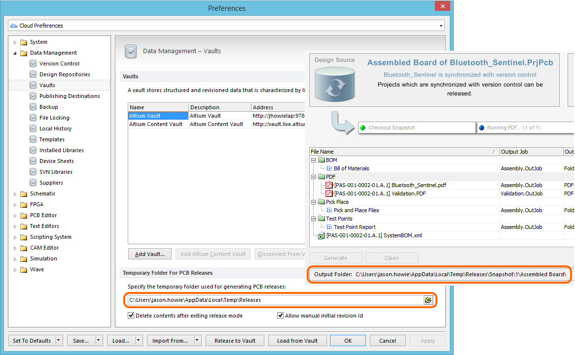
Specify a temporary folder used for generating release data (default folder illustrated).
Assuming all is generated successfully, the resulting data, as well as the snapshot, are then committed to the target vault – essentially copied from the temporary folder to the vault. Upon committal, the Release Summary dialog will appear, providing a listing of the data that has been stored in the revision of the Item in the vault. As the process is fully automated, the risk of errors associated with a manual release process are no longer a consideration. Full validation, full checking. The data sent to manufacturing is exactly what it needs to be, to produce the product exactly as you designed it.

Successful release of a configuration of a design project. The release data (snapshot + outputs) is committed to the target vault, stored in the targeted Item Revision. The released documents and design snapshot are summarized in the Release Summary dialog.
Once released successfully, the lifecycle state of the revision of the targeted Item will change from Planned to Released or New From Design (depending on the particular lifecycle definition employed). This is reflected in the tab for the configuration.

The tab for the configuration is updated to reflect the lifecycle state of the newly-released Item Revision. The example shown is for a lifecycle definition other than Basic Lifecycle.
For a released Item, detailed information and lifecycle status controls regarding the Item (and all its revisions) are available in the Item view. From the PCB Release view, this can be accessed by:
- Clicking on the header text in the Target Vault region (
Revision <Revision ID> of <Item ID>). - Clicking on the Item or Revision text in the configuration tab region.
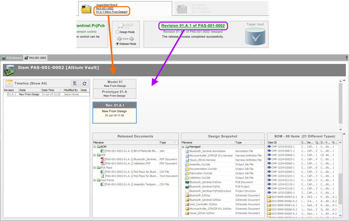
Click a hyperlink to access the Item view, containing a full history of the Item, with both graphical representation of its revisions and lifecycle states, as well as a textual-based timeline.
Facilitating a Solid Audit Trail
Whenever a new revision of an Item is generated, during the release process Altium Designer records the version control repository address, and revision of the project, and commits this information to the target vault. This method means that at any point in the future it is possible to retrieve an identical snapshot of all files in the design project from version control. To put this another way, it is possible to identify the point in time at which any given configuration of the PCB design was released, go back to this point and retrieve, modify and re-release that configuration with the correct dependencies.
Two files, stored in the Design Repository, effectively 'record' the release at the time the release data is committed to the Item Revision in the target vault:
Item ID-Revision ID[ProjectName].ReleaseInfo– this file is release-specific. It lists all files that are generated and checked in as part of the commit stage of the board design release process, as well as the version control repository addresses (URLs) of the source design documents and dependencies (where known)._Release.log– this file is project-specific. It provides a running log of all releases of that particular project, in terms of released configuration name and the revision of the Item that the data was released into.
These files are checked into the Design Repository in a sub-folder of the design project, named ReleaseInfo.
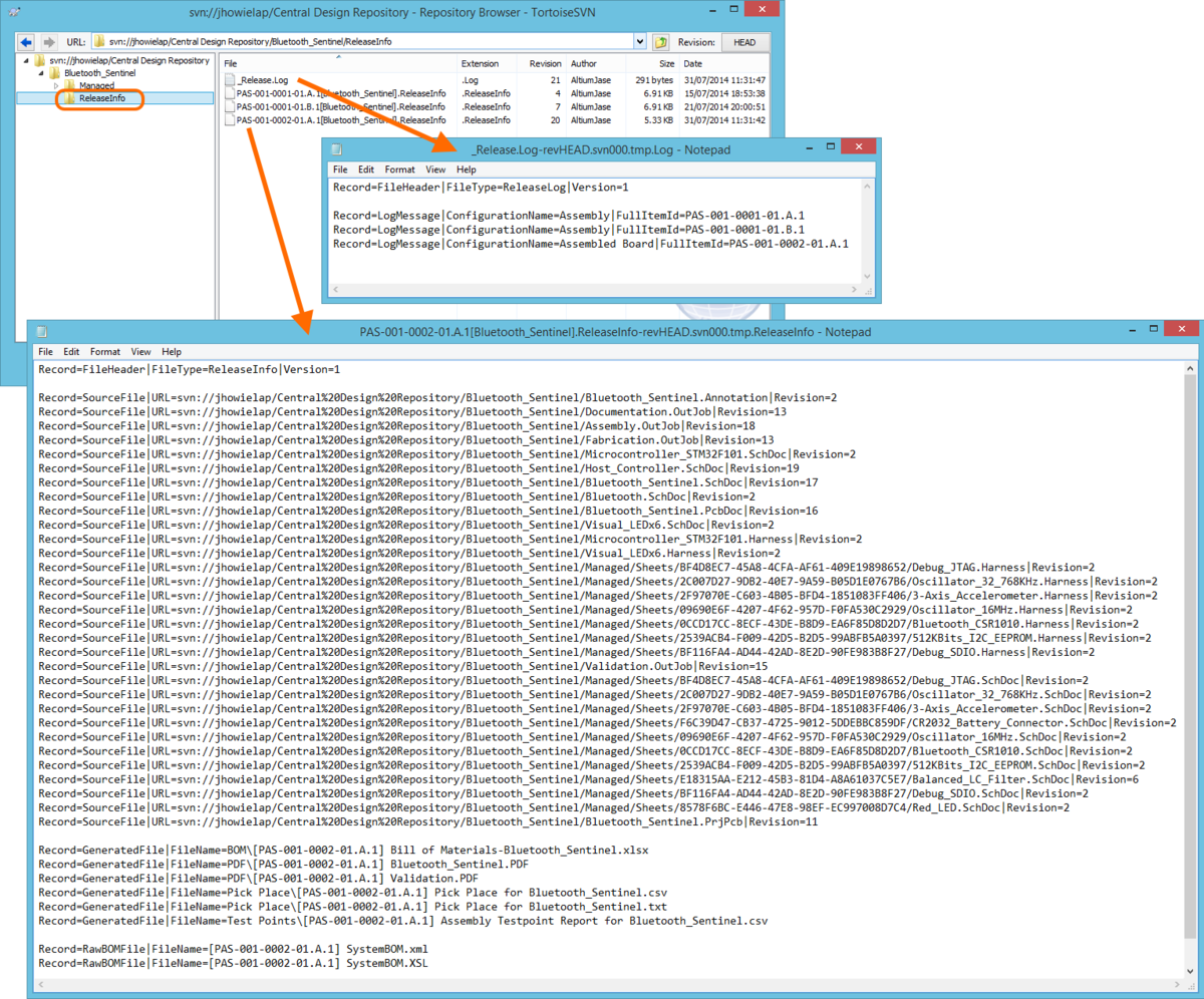
Information about a specific release is stored in the Design Repository within an associated .ReleaseInfo file. All releases for a design project can be found in that project's _Release.log file.
Viewing the revisions of the _Release.log file for a project – through the Storage Manager panel – will effectively show you a history of all releases of that project.

A history of releases for a project - quickly accessed through the Storage Manager panel.