Using the PCB API
Contents
- Using the PCB Editor Interfaces
- PCBServer function
- Invoking Properties and Methods of PCB Interfaces
- The PCB Database system
- PCB and Library documents
- Loading PCB or PCB Library documents
- Creating PCB or PCB Library documents
- Checking the type of PCB documents
- Setting a Document Dirty
- Refreshing a document programmatically
- PCB Objects
- Accessing PCB Objects
- Creation of a New PCB Object
- How the above code works
- Creating/deleting Objects and updating the PCB Editor’s Undo system
- One Undo sequence
- Multiple Undos sequence
- Modifying PCB Design Objects in code
- PCB interactive feedback using the Mouse
- Activating the PCB API
Parent page: Using the Altium Designer API
Using the PCB Editor Interfaces
The PCB API allows a programmer to fetch or modify PCB objects and their attributes from a PCB document. The objects shown on a document are stored in its corresponding design database.
The PCB interfaces exposed by the PCB editor refer to opened PCB documents and the objects on them. The PCB API derives its functionality from the base Altium Designer API which contains interface objects declarations and type declarations. An interface is a means of access to an object in memory. To have access to the PCB server and massage certain PCB design objects, you need to invoke the PCBServer function which extracts the IPCB_ServerInterface interface.
This is the main interface and contains many interfaces within it. With this interface, you can proceed further by iterating for certain PCB objects.
The IPCB_ServerInterface and IPCB_Board interfaces are the main interfaces that you will be dealing with when you are extracting data from a PCB or PCB Library document. Below is the simplified PCB object interface hierarchy.
Simplified PCB Objects Interfaces hierarchy
IPCB_Primitive
        IPCB_Arc
        IPCB_DifferentialPair
        IPCB_FromTo
        IPCB_Via
        IPCB_Group
               IPCB_Coordinate
               IPCB_Dimension
               IPCB_Net
               IPCB_Polygon
                      IPCB_BoardOutline
               IPCB_Component
               IPCB_LibComponent
        IPCB_RectangularPrimitive
               IPCB_EmbeddedBoard
               IPCB_Text
               IPCB_Fill
        IPCB_Region
               IPCB_ComponentBody
PCBServer function
When you need to work with PCB design objects in Altium Designer, the starting point is to invoke the PCBServer function and with the IPCB_ServerInterface interface, you can extract the all other derived PCB interfaces that are exposed in the IPCB_ServerInterface interface. For example, to get an access to the current PCB document open in Altium Designer, you would invoke the GetCurrentPCBBoard method from the IPCB_ServerInterface interface object.
- The
IPCB_ServerInterfaceinterface is the main interface in the PCB API. To use PCB interfaces, you need to obtain theIPCB_ServerInterfaceobject by invoking thePCBServerfunction. TheIPCB_ServerInterfaceinterface is the gateway to fetching other PCB objects. - The
IPCB_Primitiveinterface is a generic interface used for all PCB design object interfaces. - The
IPCB_Boardinterface points to an existing PCB document in Altium Designer.
GetCurrentPCBBoard example
TheServer := PCBServer.GetCurrentPCBBoard; If TheServer = Nil Then Exit; TheBoard := PCBBoard. GetCurrentPCBBoard If TheBoard = Nil The Exit; TheFileName := TheBoard. GetState_FileName; For detailed information on PCB API, refer to the Technical Reference - PCB API document.
Invoking Properties and Methods of PCB Interfaces
For each PCB object interface, there will be methods and properties listed (not all interfaces will have both methods and properties listed, that is, some interfaces will only have methods).
A class method is a procedure or function that operates on a class rather than on specific instances of the class.
A property of an object interface is like a variable, you get or set a value in a property, but some properties are read only properties meaning they can only return values but cannot be set. A property is implemented by its Get and Set methods
For example, the IPCB_Component interface has a Height property and two associated methods GetState_Height and SetState_Height:
Function GetState_Height : TCoord; Procedure SetState_Height (Value : TCoord); Property Height : TCoord Read GetState_Height Write SetState_Height; Another example is that the Selected property has two methods Function GetState_Selected : Boolean; and Procedure SetState_Selected (B : Boolean);
Object Properties example
PCBComponent.Selected := True //set the value ASelected := PCBComponent.Selected //get the value The IPCB_Primitive is the base interface for all other PCB design object interfaces such as IPCB_Track and IPCB_Component.
For example the Selected property and its associated Function GetState_Selected : Boolean; and Procedure SetState_Selected (B : Boolean); methods declared in the IPCB_Primitive interface are inherited in the descendant interfaces such as IPCB_Component and IPCB_Pad interfaces.
This Selected property is not in the IPCB_Component, but you will notice that the IPCB_Component is inherited from IPCB_Primitive and this interface has a Selected property along with its associated methods (GetState function and SetState procedure).
If you can't find a method or a property in an object interface that you expect it to be in, the next step is to look into the base IPCB_Primitive interface — defines all the interfaces that are exposed and can be used to access most of the objects in PCB.
The PCB Database system
The database system is the heart of the PCB editor and this system stores all of the information about the PCB document. The objects in the database system are a direct representation of the objects on the PCB document.
The database system of the PCB editor stores primitive objects and group objects such as pads, vias, tracks, arcs, fills, text, components, nets, coordinates, dimensions, polygons, from tos, manual from-tos, classes, rules, violations and embedded objects. This primary database is a flat database which is composed of two different data structures.
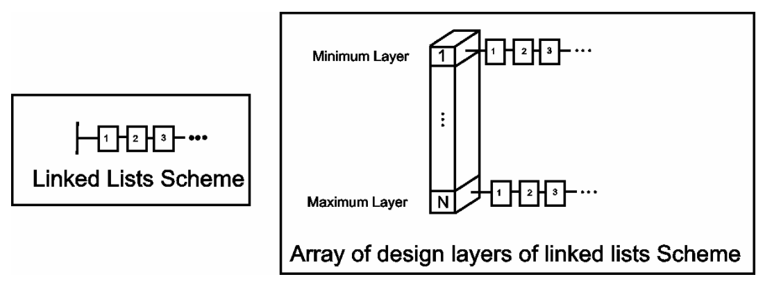
The Primary Storage System has an array of linked lists. Each layer represents a linked list of PCB objects.
The first structure on the left of the figure above consists of separate singular linked lists of vias, components, nets, coordinates, dimensions, classes, rules, from-tos and connections. The second structure on the right of the figure above consists of an array of linked lists of the same kind of PCB objects. Each array exists separately for track, arc, fill, text string, pad and polygon objects. This second data structure is optimized for performance reasons.
The secondary database system is a spatial database. For each layer in the spatial database, there is a container which is a spatial or quad tree that can store any kind of PCB object. This secondary database is optimised for fast access of PCB objects. The type of database is chosen automatically depending on which specific PCB functions are being invoked.
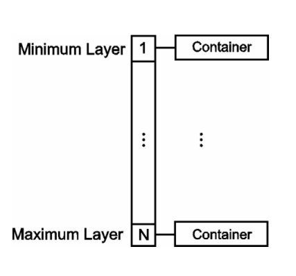
The Secondary Storage System has spatial containers for each design layer.
PCB and Library documents
There are two types of documents in the PCB editor, the PCB document and the PCB Library document. Dealing with PCB documents is straightforward.
The concept of handling a PCB Library document is a bit more involved since each PCB footprint (a component with an undefined designator) occupies one PCB library document within a PCB library file. Note that you can only place tracks, arcs, fills, texts, pads and vias on a library document.
Loading PCB or PCB Library documents
There are other situations when you need to programmatically open a specific document. This is facilitated by using the Client object and invoking one of its methods such as Client.OpenDocument and Client.ShowDocument methods.
Opening a text document, you pass in the ‘Text’ string along with the full file name string. For PCB and PCB Library documents, the ‘PCB’ and ‘PCBLIB’ strings respectively need to be passed in along with the full file name string. For Schematic and Schematic Library documents, the ‘SCH’ and ‘SCHLIB’ strings respectively need to be passed in along with the full file name string.
Since the parameters for some of the functions are null terminated types and often the strings are TPCBString types, you will need to typecast these strings as PChar type.
In the code snippet below, the IServerDocument.DM_FullPath method returns a TPCBString, and this parameter is typecasted as a PChar in the Client.OpenDocument method.
Opening a Text Document using Client.OpenDocument method
Var ReportDocument : IServerDocument; Begin ReportDocument := Client.OpenDocument('Text',PChar(FileName)); If ReportDocument <> Nil Then Client.ShowDocument(ReportDocument); End See the script examples in the Scripts\DelphiScript Scripts\PCB\ folder.
Creating PCB or PCB Library documents
There are situations when you need to programmatically create a blank document, this is facilitated by using the CreateNewDocumentFromDocumentKind function. For example, to creating a text document pass in the ‘Text’ string.
CreateNewDocumentFromDocumentKind code example
Var Document : IServerDocument; Kind : TPCBString; Begin //The available Kinds are PCB, PCBLib, SCH, SchLib, TEXT,... Kind := ‘PCB’; Document := CreateNewDocumentFromDocumentKind(Kind); End; Create a blank PCB and add to the current Project code example
Var Doc : IServerDocument; Project : IProject; Path : TPCBString; Begin If PCBServer = Nil then Exit; Project := GetWorkSpace.DM_FocusedProject; If Project <> Nil Then Begin Path := GetWorkSpace.Dm_CreateNewDocument(‘PCB’); Project.DM_AddSourceDocument(Path); Doc := Client.OpenDocument(Pchar(‘PCB’,PChar(Path)); Client.ShowDocument(Doc); End; // do what you want with the new document. End; See the script examples in the Scripts\DelphiScript Scripts\PCB\ folder.
Checking the type of PCB documents
You can use the GetCurrentPCBBoard function from the PCBServer object and with the interface object (IPCB_Board) you can invoke the IsLibrary method to check whether the current PCB document is a PCB Library type document or not.
IsLibrary method example
// check if a PCB Library document exists. Board := PCBServer.GetCurrentPCBBoard; If Board = Nil Then Exit; If Not (Board.IsLibrary) Then ShowMessage('This is not a PCBLIB document'); Document Kind method code example
If StrPas(Client.CurrentView.Kind) <> UpperCase('PCBLib') Then Exit; This code snippet uses the Client.CurrentView.Kind method to find out the current document’s type.
Setting a Document Dirty
There are situations when you need to programmatically set a document dirty so when you close Altium Designer, it prompts you to save this document. This is facilitated by setting the ServerDocument.Modified to true.
Document’s Modified Property code example
Var AView : IServerDocumentView; AServerDocument : IServerDocument; Begin // grab the current document view. AView := Client.GetCurrentView; //grab the owner server document. AServerDocument := AView.OwnerDocument; // set the document dirty. AServerDocument.Modified := True; End; See the script examples in the Scripts\DelphiScript Scripts\PCB\ folder.
Refreshing a document programmatically
When you place or modify objects on a PCB document, you often need to do a refresh of the document. An example below demonstrates one way to update the document.
Refresh a PCB document in a script
// Refresh PCB screen Client.SendMessage('PCB:Zoom', 'Action=Redraw' , 255, Client.CurrentView); PCB Objects
The PCB design objects are stored inside the database of the currently active PCB document in the PCB editor. Each design object has a handle. These handles allow you to access and change the object’s properties.
A PCB object is either a primitive or a group object. A primitive is a basic PCB object which could be one of the following: tracks, pads, fills, vias and so on.
A group object can be a component, dimension, co-ordinate, polygon or a net object and each group object is composed of primitives. Each group object also has its own small database that stores primitives. A component is a group object and is therefore composed of primitives.
Accessing PCB Objects
Iterators provide a way of accessing the elements of an aggregate object sequentially without exposing its underlying representation. With regards to the PCB editor’s database system, the use of iterators provides a compact method of accessing PCB objects without creating a mirror database across the API.
The main function of an iterator is to traverse through the database to fetch certain PCB objects by traversing the database inside the PCB editor from the outside.
There are four types of iterators:
- Board iterators
- Spatial iterators
- Group iterators
- Library iterators
Board iterators are used to conduct global searches, while spatial iterators are used to conduct restricted searches within a defined boundary. Group iterators are used to conduct searches for child objects within a group object such as a component and library iterators are used to conduct a search within a PCB library document within a PCB library.
Board Iterator example in a Server project
Var Board : IPCB_Board; Pad : IPCB_Primitive; Iterator : IPCB_BoardIterator; Begin // retrieve the current board's handle Board := PCBServer.GetCurrentPCBBoard; If Board = Nil Then Exit; // retrieve the iterator handle Iterator := Board.BoardIterator_Create; Iterator.AddFilter_ObjectSet([ePadObject]); Iterator.AddFilter_LayerSet(AllLayers); Iterator.AddFilter_Method(eProcessAll); // search and count pads Pad := Iterator.FirstPCBObject; While (Pad <> Nil) Do Begin // do what you want with the fetched pad Pad := Iterator.NextPCBObject; End; Board.BoardIterator_Destroy(Iterator); See the script examples in the Scripts\DelphiScript Scripts\PCB\ folder.
Creation of a New PCB Object
PCB objects created using the PCB API will need to follow a few simple steps to ensure that the database system of the PCB editor will successfully register these objects. An example is shown to illustrate the steps involved in creating a new PCB object. The code demonstrates the paramount role of the creation of a board object before any PCB objects are to be created, destroyed or modified. If there is no board object, the database system inside the PCB editor will not be updated and the current PCB document will not be affected either.
This code snippet demonstrates the registration and placement of a Via object (which is one of the PCB editor’s design objects) onto a PCB document. This example will also illustrate the concept of object handles.
PCBObjectFactory method example
Procedure CreateAViaObject; Var Board : IPCB_Board; Via : IPCB_Via; Begin Board := PCBServer.GetCurrentPCBBoard; If Board = Nil Then Exit; (* Create a Via object*) Via := PCBServer.PCBObjectFactory(eViaObject) As IPCB_Via; Via.X := MilsToCoord(1000); Via.Y := MilsToCoord(1000); Via.Size := MilsToCoord(50); Via.HoleSize := MilsToCoord(20); Via.LowLayer := eTopLayer; Via.HighLayer := eBottomLayer; Board.AddPCBObject(Via); End; How the above code works
The board is fetched which is a representation of an actual PCB document and then a PCBObjectFactory method is called from the IPCB_ServerInterface (representing the PCB editor) and a copy of the Via object is created.
You can change the attributes of this new object and then you can add this new object in the PCB database.
To ensure that the PCB editor’s database system registers this new via object, we need to add this via object into the board object, by using the board object’s AddPCBObject method the via object parameter. Once this method has been invoked, this new Via object is now a valid object on the current PCB document.
To actually remove objects from the database, invoke the Board.RemovePCBObject method and pass in the parameter of a reference to an actual PCB object.
See the script examples in the Scripts\DelphiScript Scripts\PCB\ folder.
Creating/deleting Objects and updating the PCB Editor’s Undo system
The CreateAVia addon above example does not refresh the Undo system in the PCB editor, to do this, you will need to employ the SendMessageToRobots method to send messages into the PCB editor server to inform the datastructure that new PCB objects have been added to the PCB document.
One Undo sequence
The sequence is as follows for a one big undo operation:
- Invoke the
PCBServer.PreProcessmethod which initializes the robots in the PCB server once - For each new object added, send a
PCBM_BoardRegisterationmessage - Invoke the
PCBServer.PostProcessmethod which cleans up the robots in the PCB server once
Multiple Undos sequence
The sequence is as follows for multiple step undo operation, i.e. for each PCB creation, do the four steps:
- Invoke the
PreProcessmethod which initializes the Robots in the PCB server. - Add a new object.
- Send a
PCBM_BoardRegisterationmessage. - Invoke the
PostProcessmethod which cleans up the robots in the PCB server.
Repeat Steps 1-4 for each PCB object creation.
Adding two Fill Objects and refreshing the Undo system in PCB Editor
Board := PCBServer.GetCurrentPCBBoard; If Board = Nil Then Exit; PCBServer.PreProcess; Fill := PCBServer.PCBObjectFactory(eFillObject) as IPCB_Fill; Fill.X1Location := MilsToCoord(4000); Fill.Y1Location := MilsToCoord(4000); Fill.X2Location := MilsToCoord(4400); Fill.Y2Location := MilsToCoord(4400); Fill.Rotation := 0; Fill.Layer := eTopLayer; Board.AddPCBObject(Fill1); PCBServer.SendMessageToRobots( Board.I_ObjectAddress, c_Broadcast, PCBM_BoardRegisteration, Fill1.I_ObjectAddress); Fill2 := PCBServer.PCBObjectFactory(eFillObject); Fill.X1Location := MilsToCoord(5000); Fill.Y1Location := MilsToCoord(3000); Fill.X2Location := MilsToCoord(5500); Fill.Y2Location := MilsToCoord(4000); Fill.Rotation := 45; Fill.Layer := eTopLayer; Board.AddPCBObject(Fill2); PCBServer.SendMessageToRobots( Board.I_ObjectAddress, c_Broadcast, PCBM_BoardRegisteration, Fill2.I_ObjectAddress); PCBServer.PostProcess; See the script examples in the Scripts\DelphiScript Scripts\PCB\ folder.
Removal of Objects code example
PCBServer.PreProcess; Try Track := Iterator.FirstPCBObject As IPCB_Track; While Track <> Nil Do Begin OldTrack := Track; Track := Iterator.NextPCBObject As IPCB_Track; CurrentPCBBoard.RemovePCBObject(OldTrack); PCBServer.SendMessageToRobots(Board.I_ObjectAddress, c_BroadCast, PCBM_BoardRegisteration, OldTrack.I_ObjectAddress); End; Finally CurrentPCBBoard.BoardIterator_Destroy(Iterator); End; PCBServer.PostProcess; See the script examples in the Scripts\DelphiScript Scripts\PCB\ folder.
Modifying PCB Design Objects in code
To modify PCB objects on a current PCB document, you will need to invoke certain methods in a certain order to ensure the Undo/Redo system is up to date when a PCB object’s attributes have been modified programmatically.
The Modification of a PCB Object Sequence is as follows:
- Invoke the
PreProcessmethod and Initialize the robots in the PCB server - Send a
PCBM_BeginModifymessage - Modify the PCB object
- Send a
PCBM_EndModifymessage - Invoke the
PostProcessmethod to clean up the robots in the PCB server
Changing PCB Object’s Attributes example
Procedure ModifyObject; Begin PCBServer.PreProcess; PCBServer.SendMessageToRobots(Fill.I_ObjectAddress, c_Broadcast, PCBM_BeginModify ,c_NoEventData); Fill.Layer := eBottomLayer; PCBServer.SendMessageToRobots(Fill.I_ObjectAddress, c_Broadcast, PCBM_EndModify , c_NoEventData); //Clean up the robots in the PCB editor. PCBServer.PostProcess; End; When you change the properties of a PCB object on a PCB document, it is necessary to employ the PCBServer.SendMessageToRobots function to update the various subsystems of the PCB system such as the Undo/Redo system and setting the document as dirty so the document can be saved. Learn more about the SendMessageToRobots method of the IPCB_ServerInterface in the Technical Reference - PCB API document.
Remember, the PCB API only can be used to work on a currently open PCB document in Altium Designer. If you need to fetch specific PCB documents, you will need the Client object’s OpenDocument and ShowDocument methods to open and display a document.
Procedure OpenAndShowPCBDocument(AFileName : String); Var Document : IServerDocument; Begin If Client = Nil Then Exit; Document := Client.OpenDocument('PCB',AFileName,False); If Document <> Nil Then Client.ShowDocument(Document); End; See the script examples in the Scripts\DelphiScript Scripts\Sch\ folder.
PCB interactive feedback using the Mouse
To monitor the mouse movement and clicks from your script, the IPCB_Board document interface has several interactive feedback methods:
GetObjectAtCursorGetObjectAtXYAskUserIfAmbiguousChooseRectangleByCornersChooseLocation
The GetObjectAtCursor returns you the interface of an object where the PCB system has detected that this object has been clicked upon.
The GetObjectAtXYAskUserIfAmbiguous method does the same function as the GetObejctAtCursor except that if there are objects occupying the same region on the PCB document, then this method prompts you with a dialog with a list of objects to choose before returning you the object interface. You have the ability to control which objects can be detected and which layers can be detected and what type of editing action the user has been doing.
The ChooseRectangleByCorners method prompts you to choose the first corner and the final corner and then the X1,Y1, X2 and Y2 parameters are returned.
The ChooseLocation method prompts you to click on the PCB document and then the X1,Y1 coordinates of the mouse click are returned.
ChooseRectangleByCorners example in a Server project
Var Board : IPCB_Board; SpatialIterator : IPCB_SpatialIterator; X1,Y1,X2,Y2 : TCoord; ASetOfLayers : TLayerSet; ASetOfObjects : TObjectSet; Track : IPCB_Track; TrackCount : Integer; Begin //Spatial iterator queries PCB data within X1,Y1,X2,Y2 constraints Board := PCBServer.GetCurrentPCBBoard; If Board = Nil Then Exit; TrackCount := 0; If Not (Board.ChooseRectangleByCorners('Please select the first corner', 'Please select the final corner', X1,Y1,X2,Y2)) Then Exit; ASetOfLayers := [eTopLayer,eBottomLayer]; ASetOfObjects := [eTrackObject]; SpatialIterator := Board.SpatialIterator_Create; SpatialIterator.AddFilter_Area(X1,Y2,X2,Y2); SpatialIterator.AddFilter_ObjectSet(ASetOfObjects); SpatialIterator.AddFilter_LayerSet(ASetOfLayers); Track := SpatialIterator.FirstPCBObject as IPCB_Track; While Track <> Nil Do Begin TrackCount := TrackCount + 1; Track := SpatialIterator.NextPCBObject as IPCB_Track; End; Board.SpatialIterator_Destroy(SpatialIterator); Showinfo(InTtoStr(TrackCount)); End; See the script examples in the Scripts\DelphiScript Scripts\PCB\ folder.
Activating the PCB API
There are situations when Altium Designer has no PCB documents opened, meaning that the PCB Editor has not been loaded and that the PCB API is not active.
You will then need to manually start the server to have access to the PCB API. Starting up the PCB server to activate the PCB API is done by invoking the Client.StartServer method.
Starting up the PCB server in Altium Designer
If PCBAPI_GetCurrentEditorWindow = 0 Then Begin Client.StartServer('PCB'); Board := PCBServer.GetCurrentPCBBoard; If Board = Nil Then Exit; End; For more information, consult the PCB API Reference document within the Altium Designer API Reference.