PCB Project Configurations
Contents
Parent article: Board Design Release
PCB design projects (*.PrjPcb) are design-side entities, containing the source documents that collectively define the object being designed. They represent the design team's intent on how the system should be built and how it should work. Their parametric nature – through the use of defined variants and Output Job files – enables a single design project to be the source of multiple real-world production Items – the tangible products that are made and sold. For example, a single PCB design project can be the source of not only a fabricated 'bare' board, but quite possibly one or more assembled boards – each a unique production Item in its own right. Providing a formal configuration structure, to map from source PCB project to these Items, Altium Designer employs the concept of PCB Project Configurations.
Configurations then, provide the link from the design world to the manufacturing world. Each configuration represents an Item that we want to build in the real world, defining the data that will be required by a manufacturing organization to actually build that Item. The data generated from a configuration can be considered a specific set of "instructions", with which to build the Item.
From an engineering perspective, a configuration can be summarily described as "a specific parameterized build of a PCB project". To put this a little more precisely, a PCB project configuration is a specific set of outputs for a given parameterized data source.
The Configuration Manager
Each configuration of a PCB project on the design side, maps to a specific Item on the manufacturing side. As its output is simply a generated set of instructions, or 'blueprint' for how to make the Item, a configuration simply needs to define which variant and associated project Output Job files to be used, and nominate which Item – in the chosen Altium Vault – to target.
In summary, the formal set of elements used to define a configuration for a PCB project are:
- Its name
- Which variant it uses (if any)
- The specific Item it is targeting. To successfully release, the configuration must point to a revision of that Item that is in the
Plannedstate. - Which Output Job file(s) will drive the generation of its outputs – the instructions from which the targeted Item will be produced. A particular Output Job file can also include validation outputs, by which to constrain the release process, ensuring the design source used in the release is of the highest integrity.
When releasing a board design, a configuration can map to one of three types of Item:
- Blank Board (altium-pcb-blank) – this type of Item is used to produce a fabricated bare board, containing no components.
- Assembled Board (altium-pcb-assembly) – this type of Item is used to produce a Blank Board Item that is populated with components in accordance with a generated BOM.
- PCB Design (altium-pcb-design) – this type of Item is essentially used to gather together all documentation - fabrication, assembly, and any other documentation - in a single place, a released 'master' copy of the design as it were.
All definition and management of configurations for a PCB project is performed from within the Configuration Manager dialog (Project » Configuration Manager).
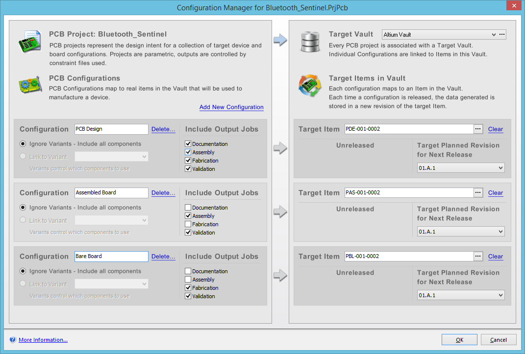
The Configuration Manager streamlines the process of defining configurations for the active PCB project.
The beauty of the Configuration Manager is its intuitive simplicity – enabling you to define the configurations you require with streamlined efficiency. For each configuration, simply specify a particular variant to be used (if applicable and/or required), assign which Output Job file(s) to be used, and browse the nominated Altium Vault to choose the Item to target (or map) the configuration to. Don't forget to give each configuration a meaningful name, so that you can easily distinguish the purpose of each!
The following sections take a closer look at using the Configuration Manager dialog.
Specifying the Location for Released Data - an Altium Vault
Related article: Altium Vault
The data generated upon releasing a design project (or rather defined configurations of that project) is stored in an Altium Vault. The Configuration Manager dialog provides a field - Target Vault - with which to specify the vault to be used. The associated drop-down lists all currently connected Altium Vaults, enabled for use by the system. Simply choose the vault required from this list.
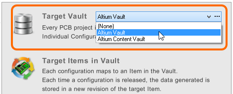
Choose which Altium Vault is used to store release data generated from the
design project.
Default Configuration
When the Configuration Manager dialog is first accessed for a PCB project, you will notice a single base configuration is automatically added – with the name Default Configuration. The configuration is set to ignore variants (that is, include all components if targeting an assembled board Item), and is not mapped to any Item. Any Output Job files you have added to the project will also be listed, but are not assigned to the configuration.
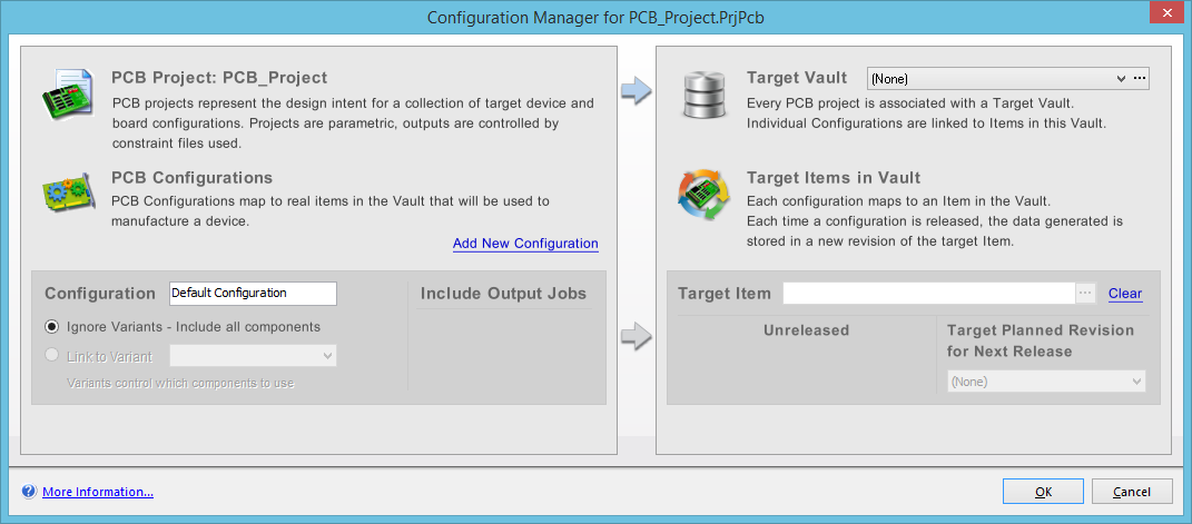
A single, default configuration is added for you, to get you up and going with configurations more quickly.
Managing Configurations
Whether adding new configurations, or needing to edit or delete existing ones, the Configuration Manager dialog provides all controls necessary to define and manage the configurations you require for your PCB project.
Adding a New Configuration
To add a new configuration, simply click on the Add New Configuration link, above the currently defined configuration(s) on the left-hand side of the dialog. An additional configuration-target Item pair will be added to the dialog – the configuration specified in a region on the left, mapping to a target Item specified in a region on the right. Each new configuration will be given a default name, in the format New Configuration, New Configuration 1, and so on.

An example of adding a new configuration.
Renaming/Deleting a Configuration
You may need to change the unique name for a configuration. For example, rather than delete the default configuration, you could simply rename it and then define it as required. To rename a configuration, simply click within its name field and type the new name as required.
To delete a configuration entirely, simply click on the Delete link, to the right of the configuration's name. A dialog will appear asking for confirmation to proceed with the deletion – click Yes, and the configuration, along with its 'paired' target Item, will be removed.
Defining a Configuration
Each configuration you define is unique and in turn must map to a unique Item in the target Altium Vault. As such, each configuration is represented by its own dedicated region on the left side of the Configuration Manager dialog, mapping to a target Item defined in a dedicated region on the right side. This 'pairing' is visually indicative of the board design release concept – a configuration of the project on the design side released into a 'planned' revision of a targeted Item in the vault.
In a Configuration region on the left side, the following information is definable:
- Name – this is the configuration's unique identifier. When other parts of the system, on the design side, refer to the configuration, they do so using this name. It is unique in the scope of the PCB project. Specify the name for a configuration when you add it. Existing configurations can be renamed as required.
- Ignore Variants – enable this option if no variant is to be used to drive output generation. When targeting an assembled board Item, this simply means that the full base design will be used, that is, all components included (fitted) on the board.
- Link to Variant – enable this option and specify the name of the variant that is to be used to drive output generation, with respect to any assigned Output Job files for the configuration. Use the drop-down associated with the field to choose from a list of all currently defined variants for the project.
- Include Output Jobs – the final part of defining a configuration is Output Job file assignment. Any Output Job files that are currently added to the PCB project are listed automatically here, by name. Each Output Job file has an associated check box. Enable a check box to assign the associated Output Job file to the configuration – that is, to specify that the Output Job file should drive the outputs of that configuration.
In the corresponding Target Item region on the right side – to which the configuration is to map – the following information is presented:
-
Target Item – this is the unique ID for an Item defined in the target vault, along with its description (if defined). This is the Item that will receive the released data or, more specifically, a planned revision of that Item. Through this Item ID, a configuration is able to map from the Design Area to the Supply Chain Area. To specify the target Item, click on the
 button at the right of the field. This will give you access to the Choose Item dialog. This dialog essentially presents a view of the target vault, and allows you to browse the vault's folder structure for the Item you want to map the configuration to.

Use the Choose Item dialog to quickly select the required target Item (and planned revision thereof).
- Last Release Information – the bottom left area of the region presents information regarding the last release of the Item, including the Item Revision ID, the release date, and the lifecycle state of that revision. If the Item has never been released, this region will simply display
Unreleased. - Target Planned Revision for Next Release – this field is used to specify a planned revision of the target Item to be used when next releasing the corresponding configuration of the design project. Remember that in order to release a configuration, the revision of the Item into which the release data is to be stored must be in the
Plannedstate. That is, it must be ready to accommodate that release data. Use the associated drop-down list to choose from all existing planned revisions of the specified Target Item.
Warnings
Adding and defining configurations for a PCB project is made very straightforward using the Configuration Manager dialog's intuitive interface. However, it is sometimes possible to encounter conflicts within or between configurations. The beauty of the dialog is that it will alert you to such occurrences, as you go, and provide hints as to the cause of such problems – enabling you to make adjustments and corrections sooner, rather than later.
The following sections consider warning-related scenarios that can occur, and be flagged, within the Configuration Manager dialog. All warnings are highlighted through use of an error dialog, that appears if you try to OK out of the dialog.
Duplicate Configuration Names
Two (or more) defined configurations for the project have the same name. Each configuration must be given a unique name.
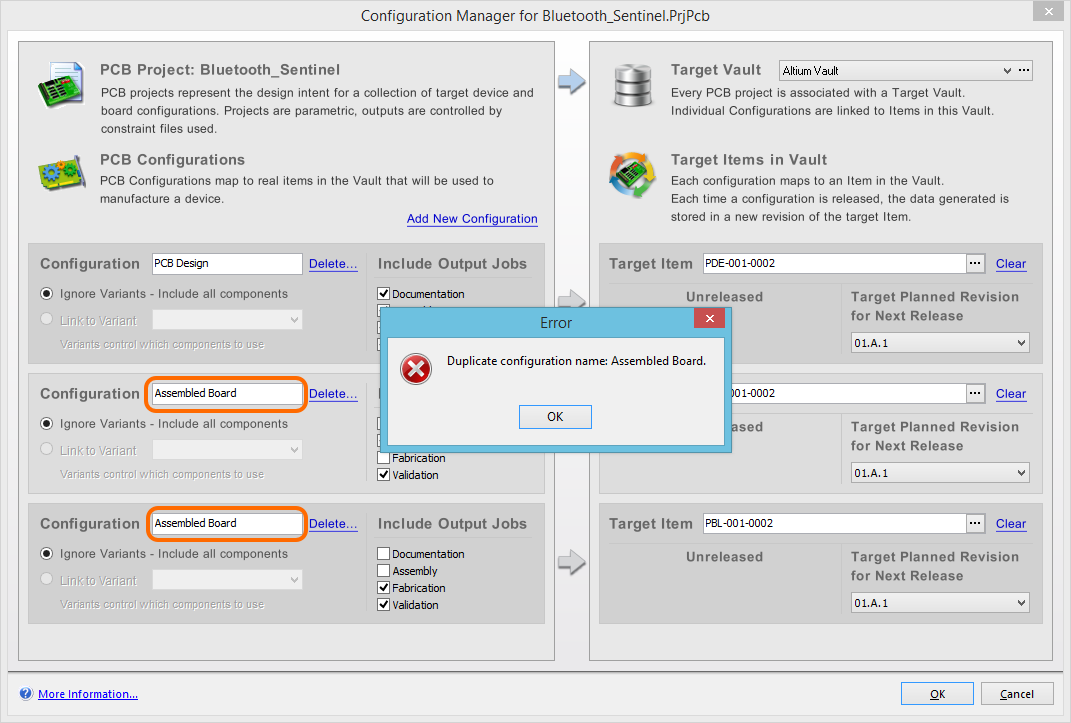
In this example, the names for the two configurations are the same (Assembled Board).
To resolve this warning, change the name for the affected configurations, such that each configuration has its own unique name.
Duplicate Target Items
Two (or more) defined configurations for the project are mapped to the same Item in the target vault. Each unique configuration must map to a unique Item in the vault.
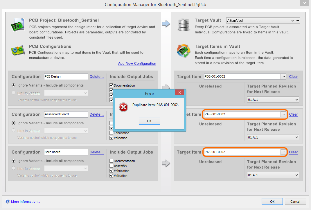
In this example, the Item ID specified for the configurations Bare Board and Assembled Board are the same (PAS-001-0002).
To resolve this warning, change the Target Item for the affected configurations, such that each configuration maps to (references) a different Item in the target vault.
Unknown Items
The Target Vault entry has been changed to [None], and all Target Items (and Target Planned Revisions of those Items) have entered an invalid state as a result.
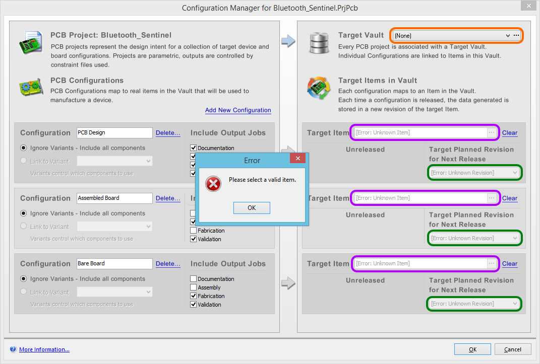
Setting the Target Vault to [None] without first clearing the Target Item links, results in an invalid Item state.
To resolve this warning:
- If wanting to release to an Altium Vault, set the Target Vault entry back to a valid Altium Vault.
- If not wanting to release to an Altium Vault, perform the following:
- Set the Target Vault entry back to a valid Altium Vault.
- Click the Clear control to the far right of each Target Item field, resulting in each field becoming blank, and the associated Target Planned Revision entry being set to (None).
- Set the Target Vault entry back to [None].