VSFFM - Frequency Modulated Sinusoidal Voltage Source Model

Model Kind
Voltage Source
Model Sub-Kind
Single-Frequency FM
SPICE Prefix
V
SPICE Netlist Template Format
@DESIGNATOR %1 %2 ?"DC MAGNITUDE"|DC @"DC MAGNITUDE"| SFFM(@OFFSET @AMPLITUDE @"CARRIER FREQUENCY" @"MODULATION INDEX" @"SIGNAL FREQUENCY") #"AC MAGNITUDE"|AC @"AC MAGNITUDE"| @"AC PHASE"
Parameters (definable at component level)
The following component-level parameters are definable for this model type and are listed on the Parameters tab of the Sim Model dialog. To access this dialog, simply double-click on the entry for the simulation model link in the Models region of the Component Properties dialog.
| DC Magnitude | DC offset used in an Operating Point Analysis. (Default = 0). |
| AC Magnitude | the magnitude of the source when used in an AC Small Signal Analysis. (Default = 1). |
| AC Phase | the phase of the source when used in an AC Small Signal Analysis. (Default = 0). |
| Offset | the DC offset of the signal generator (in Volts). (Default = 2.5). |
| Amplitude | the peak amplitude of the output voltage (in Volts). (Default = 1). |
| Carrier Frequency | the carrier frequency (in Hz). (Default = 100k). |
| Modulation Index | the modulation index (Default = 5). |
| Signal Frequency | the signal (message) frequency (in Hz). (Default = 10k). |
Notes
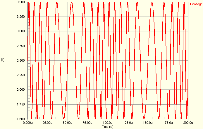
- The image below shows an example waveform produced by an FM voltage source (connected to a 1Ohm load) with the parameters set to their default values:
- The shape of the waveform is described by the following formula:
V(t) = VO + VA sin[2πFCt + MI sin(2πFSt)]
where,
tis an instance of timeVOis the DC offset of the signal generatorVAis the maximum amplitude of the output swing (excluding the DC offset)FCis the Carrier frequencyMIis the Modulation Index andFSis the Signal frequency.
The simulation-ready frequency modulated sinusoidal voltage source component (VSFFM) can be found in the Simulation Sources integrated library (\Library\Simulation\Simulation Sources.IntLib).
Examples
Consider the frequency modulated sinusoidal voltage source in the above image, with the following characteristics:
- Pin1 (positive) is connected to net
IN - Pin2 (negative) is connected to net
GND - Designator is
V1 - Offset =
0 - Carrier Frequency =
10k - Signal Frequency =
1k - All other parameters for the model are left at their default values
The entry in the SPICE netlist would be:
*Schematic Netlist:
 V1 IN 0 DC 0 SFFM(0 1 10k 5 1k) AC 1 0