ISIN - Sinusoidal Current Source Model

Model Kind
Current Source
Model Sub-Kind
Sinusoidal
SPICE Prefix
I
SPICE Netlist Template Format
@DESIGNATOR %1 %2 ?"DC MAGNITUDE"|DC @"DC MAGNITUDE"| SIN(?OFFSET/&OFFSET//0/ ?AMPLITUDE/&LITUDE//1/ ?FREQUENCY/&FREQUENCY//1K/ ?DELAY/&DELAY//0/ ?"DAMPING FACTOR"/&"DAMPING FACTOR"//0/ &PHASE) #"AC MAGNITUDE"|AC @"AC MAGNITUDE"| @"AC PHASE"
Parameters (definable at component level)
The following component-level parameters are definable for this model type and are listed on the Parameters tab of the Sim Model dialog. To access this dialog, simply double-click on the entry for the simulation model link in the Models region of the Component Properties dialog.
| DC Magnitude | DC offset used in an Operating Point Analysis. (Default = 0). |
| AC Magnitude | the magnitude of the source when used in an AC Small Signal Analysis. (Default = 1). |
| AC Phase | the phase of the source when used in an AC Small Signal Analysis. (Default = 0). |
| Offset | DC offset current of the signal generator (in Amps). (Default = 0). |
| Amplitude | peak amplitude of the sinusoid (in Amps). (Default = 1). |
| Frequency | frequency of the sinusoidal output current (in Hz). (Default = 1K). |
| Delay | delay time until the source current commences (in seconds). (Default = 0). |
| Damping Factor | the rate at which the sinusoid decreases/increases in amplitude (in 1/seconds). A positive value results in an exponentially decreasing amplitude; a negative value gives an increasing amplitude. A zero (0) value gives a constant amplitude sine wave. (Default = 0). |
| Phase | phase shift of the sinusoid at time zero (in Degrees). (Default = 0). |
Notes
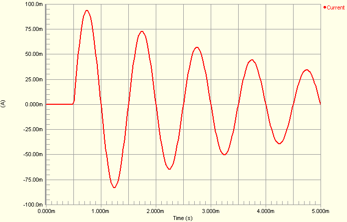
- The image below shows an example waveform produced by a sinusoidal current source (connected to a 1Ohm load). The Amplitude has been set to 100mA, the Delay set to 500.0u and the Damping Factor set to 250 - to illustrate a decreasing sinusoid. All other parameters have been left at their default values.
- The shape of the waveform is described by the following formulae:
I(t0 to tD) = IO
I(tD to tSTOP) = IO + IA e-(t- tD)THETA sin(2πF (t + tD))where,
tis an instance of timeIOis the DC offset current of the signal generatorIAis the maximum amplitude of the output swing (excluding the DC offset)Fis the FrequencytDis the Delay andTHETAis the Damping Factor
- The simulation-ready sinusoidal current source component (
ISIN) can be found in the Simulation Sources integrated library (Library\Simulation\Simulation Sources.IntLib).
Examples
Consider the sinusoidal voltage source in the above image, with the following characteristics:
- Pin1 (positive) is connected to net
GND - Pin2 (negative) is connected to net
INPUT - Designator is
Iin - Amplitude =
1m - Frequency =
10k - All other parameters for the model are left at their default values.
The entry in the SPICE netlist would be:
*Schematic Netlist:
 Iin 0 INPUT DC 0 SIN(0 1m 10K 0 0 0) AC 1 0