CLIMITER - Controlled Limiter (Single-Ended IO)

Model Kind
General
Model Sub-Kind
Generic Editor
SPICE Prefix
A
Model Name
CLIMIT
SPICE Netlist Template Format
@DESIGNATOR %1 %2 %3 %4 @"DESIGNATOR"CLIMIT
 .MODEL @"DESIGNATOR"CLIMIT climit (?in_offset|in_offset=@in_offset| ?gain|gain=@gain| ?upper_delta|upper_delta=@upper_delta| ?lower_delta|lower_delta=@lower_delta| ?limit_range|limit_range=@limit_range| ?fraction|fraction=@fraction|)
Parameters (definable at component level)
The following component-level parameters are definable for this model type and are listed on the Parameters tab of the Sim Model dialog. To access this dialog, simply double-click on the entry for the simulation model link in the Models region of the Component Properties dialog.
| In_Offset | input offset (Default = 0). |
| Gain | gain (default = 1). |
| Upper_Delta | output upper delta (Default = 0). |
| Lower_Delta | output lower delta (Default = 0). |
| Limit_Range | upper and lower smoothing range (Default = 1.0e-6). |
| Fraction | used to control whether the limit range is specified as a fractional (TRUE) or absolute (FALSE) value. (Default = FALSE). |
Notes
This model is similar in function to the Gain function. However, the output is restricted to the range specified by the output lower and upper limits (cntl_lower and cntl_upper pins of the device). The input signal can be either a single-ended current or single-ended voltage signal.
The Limit_Range is the value below the cntl_upper limit and above the cntl_lower limit at which smoothing of the output begins. A minimum positive value of current/voltage must exist between the cntl_upper and cntl_lower inputs, at all times. The Limit_Range therefore represents the delta, with respect to the output level, at which smoothing occurs. For example, for an input Gain of 2, Limit_Range of 0.1V and output limits of 1V (on pin cntl_upper) and -1V (on pin cntl_lower), the output will begin to smooth out at +/-0.9 V.
The input values arriving at the cntl_upper and cntl_lower pins of the device are tested to verify that they are far enough apart to guarantee a linear range between them. The range is calculated as:
(cntl_upper - Upper_Delta - Limit_Range) - (cntl_lower + Lower_Delta + Limit_Range)
and must be greater than or equal to zero.
When the Limit_Range is specified as a fractional value (Fraction parameter set to TRUE), it is expressed as the calculated fraction of the difference between cntl_upper and cntl_lower.
Examples
Consider the controlled limiter in the above image, with the following characteristics:
- Pin1 (input) is connected to net
In - Pin2 (cntl_upper) is connected to net Vupper
- Pin3 (cntl_lower) is connected to net Vlower
- Pin4 (output) is connected to net
Out - Designator is
U1 - Gain =
2 - Limit_Range =
0.1 - All other model parameters are left at their inherent defaults
The entry in the SPICE netlist would be:
*Schematic Netlist:
 AU1 IN VUPPER VLOWER OUT AU1CLIMIT
 .MODEL AU1CLIMIT climit (in_offset=0 gain=2 upper_delta=0 lower_delta=0
 + limit_range=0.1 fraction=FALSE)
The effect of the function can be seen in the resultant waveforms obtained by running a transient analysis of the circuit.
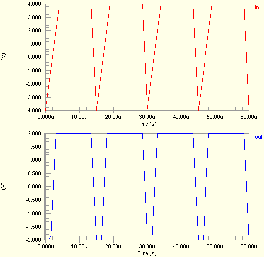
In this example, the following analysis parameters on the Transient/Fourier Analysis page of the Analyses Setup dialog have been used:
- Transient Start Time - set to
0.000 - Transient Stop Time - set to
60.00u - Transient Step Time - set to
2.000u - Transient Max Step Time - set to
2.000u
With the exception of the Initial Value parameter (set to -4V), the Pulsed Value parameter (set to 4V) and the Period parameter (set to 15us), all other parameters for the Pulse Voltage Source have been left at their defaults.