VPWL - Piecewise Linear Voltage Source Model

Model Kind
Voltage Source
Model Sub-Kind
Piecewise Linear
SPICE Prefix
V
SPICE Netlist Template Format
@DESIGNATOR %1 %2 ?"DC MAGNITUDE"|DC @"DC MAGNITUDE"| PWL(?MODELLOCATION/FILE=@MODELLOCATION//@"TIME-VALUE PAIRS"/) #"AC MAGNITUDE"|AC @"AC MAGNITUDE"| @"AC PHASE"
Parameters (definable at component level)
The following component-level parameters are definable for this model type and are listed on the Parameters tab of the Sim Model dialog. To access this dialog, simply double-click on the entry for the simulation model link in the Models region of the Component Properties dialog.
| DC Magnitude | DC offset used in an Operating Point Analysis. (Default = 0). |
| AC Magnitude | the magnitude of the source when used in an AC Small Signal Analysis. (Default = 1). |
| AC Phase | the phase of the source when used in an AC Small Signal Analysis. (Default = 0). |
| Time / Value Pairs | allows you to define the waveform by specifying a value for the voltage at various points in time. (Default pairings are: 0U 5V, 5U 5V, 12U 0V, 50U 5V, 60U 5V). |
Notes
Use this source to create an arbitrary waveform as a set of voltages at various points in time. Piecewise linear sources can take data from one of two sources:
- You can describe the waveform data as a set of points that you enter directly into the Time/Value Pairs list, on the Parameters tab of the Sim Model dialog. Use the available Add and Delete buttons to define new points or remove existing ones respectively. There is no upper limit on the number of points you can define for the waveform. The time specified for each successive point must be more positive than its predecessor. If it is not the cycle will end, excluding that and all successive points.
- You can define the waveform in an ASCII text file containing an indefinite number of points. The file must be stored in the same location as the parent project file, with the extension
.PWL. The file is referenced by entering its name (including extension) in the Model Location region's In File field, on the Model Kind tab of the Sim Model dialog.
The following criteria must be adhered to when defining the data in the file:
- Values must be entered in pairs: a time position followed by an amplitude.
- The first character of each data line must be a plus sign and each line may contain up to 255 characters.
- Values must be separated by one or more spaces or tabs.
- Values may be entered in either scientific or engineering notation.
- Comment lines may be added by making the first character of the line an asterisk .
The following example illustrates the typical format for the content in a .pwl file:
* Random Noise Data
| + 0.00000e-3 | 0.6667 | 0.00781e-3 | 0.6372 | 0.01563e-3 | -0.1177 |
| + 0.02344e-3 | -0.6058 | 0.03125e-3 | 0.2386 | 0.03906e-3 | -1.1258 |
| + 0.04688e-3 | 1.6164 | 0.05469e-3 | -0.3136 | 0.06250e-3 | -1.0934 |
- The image below shows an example waveform produced by a PWL voltage source (connected to a 1Ohm load) with the parameters set to their default values:
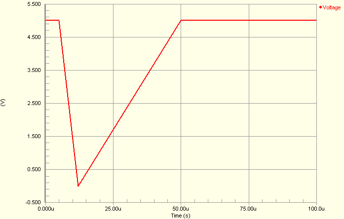
- The value for the voltage at intermediate values of time is calculated using linear interpolation on input values.
- The value of the voltage at time points subsequent to the last time point defined, will be the voltage value defined for that last time point. Similarly, if the waveform has been described starting at a time other than zero, all points in time back to zero will have that voltage which is defined for the first time point of the waveform.
- The simulation-ready piecewise-linear voltage source component (
VPWL) can be found in the Simulation Sources integrated library (\Library\Simulation\Simulation Sources.IntLib).
Examples
Consider the piecewise-linear voltage source in the above image, with the following characteristics:
- Pin1 (positive) is connected to net IN
- Pin2 (negative) is connected to net GND
- Designator is V2
- Time/Value Pair entries are:
| Time (s) | Voltage (V) |
| 0 | .1 |
| 2m | .3 |
| 4m | 1 |
| 6m | 1.5 |
| 8m | .5 |
| 10m | 2.5 |
| 12m | 4 |
| 14m | .1 |
- All other parameters for the model are left at their default values.
The entry in the SPICE netlist would be:
*Schematic Netlist:
 V2 IN 0 DC 0 PWL(0 .1 2m .3 4m 1 6m 1.5 8m .5 10m 2.5 12m 4 14m .1) AC 1 0