MULTR - Multiplier (Differential IO)

Model Kind
General
Model Sub-Kind
Spice Subcircuit
SPICE Prefix
X
Model Name
MULTR
SPICE Netlist Template Format
@DESIGNATOR %1 %2 %3 %4 %5 %6 @MODEL #|PARAMS:| ?x_offset|x_offset=@x_offset| ?y_offset|y_offset=@y_offset| ?x_gain|x_gain=@x_gain| ?y_gain|y_gain=@y_gain| ?out_gain|out_gain=@out_gain| ?out_offset|out_offset=@out_offset|
Parameters (definable at component level)
The following component-level parameters are definable for this model type and are listed on the Parameters tab of the Sim Model dialog. To access this dialog, simply double-click on the entry for the simulation model link in the Models region of the Component Properties dialog.
| X_Offset | X input offset (Default = 0). |
| Y_Offset | Y input offset (Default = 0). |
| X_Gain | X input gain (Default = 1). |
| Y_Gain | Y input gain (Default = 1). |
| Out_Gain | output gain (Default = 1). |
| Out_Offset | output offset (Default = 0). |
Notes
This is a two-input multiplier with offset and gain adjustment available on both inputs and output. It takes the inputs and processes them to obtain the output result as follows:
- The inputs are offset, in accordance with the values specified for the
X_OffsetandY_Offsetparameters. - The offset signals are then multiplied by the values for gain specified in the respective
X_GainandY_Gainparameters. - The resulting values are multiplied
- The result is then multiplied by the value specified for the
Out_Gainparameter. - The output result is then offset in accordance with the value specified for the
Out_Offsetparameter.
The process can be expressed mathematically as follows:
Output = (((X + X_Offset) * X_Gain) * ((Y + Y_Offset) * Y_Gain) * Out_Gain) + Out_Offset
This model will operate in DC, AC and Transient analysis modes only. When running an AC Small Signal analysis, the results are only valid when one of the two inputs, not both, is connected to an AC signal.
The input signals can be either differential current or differential voltage signals.
The built-in XSpice multiplier function can take two or more inputs, with no upper limit on the number of inputs considered. This particular 2-input version is defined using the hierarchical sub-circuit syntax. Within the sub-circuit definition, the XSpice Multiplier model is called and the parameters of the sub-circuit file parsed to this model.
Entering a value for a parameter on the Parameters tab of the Sim Model dialog will override its specified value in the sub-circuit file.
To check the default values of the supplied 2-input multiplier, open the appropriate sub-circuit (.ckt) file. You can view the content of this file for the model specified on the Model Kind tab of the Sim Model dialog, by clicking on the Model File tab at the bottom of the dialog. The default parameter values are listed in the .SUBCKT line.
Examples
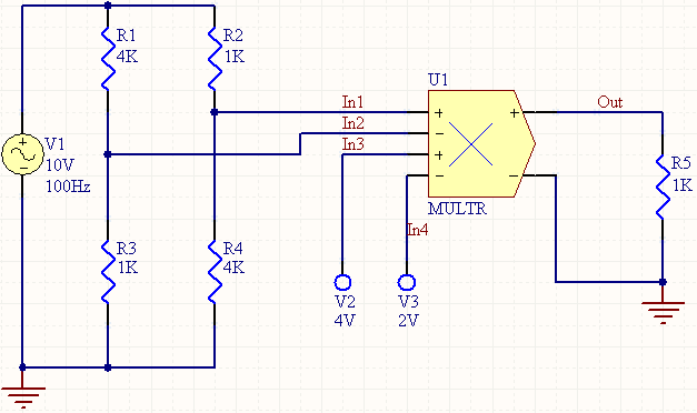
Consider the multiplier in the above image, with the following characteristics:
- Pin1 (positive a input) is connected to net
In1 - Pin2 (negative a input) is connected to net
In2 - Pin3 (positive b input) is connected to net
In3 - Pin4 (negative b input) is connected to net
In4 - Pin5 (positive output) is connected to net
Out - Pin6 (negative output) is connected to net
GND - Designator is
U1 - X_Gain =
0.5(defined on the Parameters tab) - Y_Gain =
2(defined on the Parameters tab) - Out_Gain =
2(defined on the Parameters tab) - All other parameters are left at their default values
The entries in the SPICE netlist would be:
*Schematic Netlist:
 XU1 IN1 IN2 IN3 IN4 OUT 0 MULTR PARAMS:   x_gain=0.5 y_gain=2 out_gain=2
 .
 .
 *Models and Subcircuit:
 .SUBCKT MULTR 1   2   3   4   5   6 PARAMS: x_offset=0.0 y_offset=0.0 x_gain=1.0
 + y_gain=1.0 out_gain=1.0 out_offset=0.0
 A1 [%vd(1,2) %vd(3,4)] %vd(5,6) sigmult
 .model sigmult mult(in_offset=[{x_offset} {y_offset}] in_gain=[{x_gain} {y_gain}]
 + out_gain={out_gain} out_offset={out_offset})
 .ENDS MULTR
The effect of the function can be seen in the resultant waveforms obtained by running a transient analysis of the circuit.
In this example, the following analysis parameters on the Transient/Fourier Analysis page of the Analyses Setup dialog have been used:
- Transient Start Time - set to
0.000 - Transient Stop Time - set to
50.00m - Transient Step Time - set to
200.0u - Transient Max Step Time - set to
200.0u