IPULSE - Pulse Current Source Model

Model Kind
Current Source
Model Sub-Kind
Pulse
SPICE Prefix
I
SPICE Netlist Template Format
@DESIGNATOR %1 %2 ?"DC MAGNITUDE"|DC @"DC MAGNITUDE"| PULSE(?"INITIAL VALUE"/&"INITIAL VALUE"//0/ ?"PULSED VALUE"/&"PULSED VALUE"//5/ ?"TIME DELAY"/&"TIME DELAY"//0/ ?"RISE TIME"/&"RISE TIME"//4U/ ?"FALL TIME"/&"FALL TIME"//1U/ ?"PULSE WIDTH"/&"PULSE WIDTH"//0/ ?PERIOD/&PERIOD//5U/ &PHASE) #"AC MAGNITUDE"|AC @"AC MAGNITUDE"| @"AC PHASE"
Parameters (definable at component level)
The following component-level parameters are definable for this model type and are listed on the Parameters tab of the Sim Model dialog. To access this dialog, simply double-click on the entry for the simulation model link in the Models region of the Component Properties dialog.
| DC Magnitude | DC offset used in an Operating Point Analysis. (Default = 0). |
| AC Magnitude | the magnitude of the source when used in an AC Small Signal Analysis. (Default = 1). |
| AC Phase | the phase of the source when used in an AC Small Signal Analysis. (Default = 0). |
| Initial Value | current amplitude at time zero (in Amps). (Default = 0). |
| Pulsed Value | maximum amplitude of the output swing (in Amps). (Default = 5). |
| Time Delay | delay before the source changes from Initial current value to Pulsed current value (in seconds). |
| Rise Time | the time it takes to rise from Initial current value to Pulsed current value (in seconds). Must be > 0. (Default = 4u). |
| Fall Time | the time it takes to fall from Pulsed current value back to the Initial current value (in seconds). Must be > 0. (Default = 1u). |
| Pulse Width | the time that the source remains at the Pulsed current amplitude (in seconds). (Default = 0). |
| Period | the time between the start of the first pulse and the start of the second pulse (in seconds). (Default = 5u). |
| Phase | phase shift of the waveform at time zero (in Degrees). |
Notes
- The image below shows an example waveform produced by a periodic-pulse current source (connected to a 1Ohm load). The Pulse Width has been set to 5u, the Period has been set to 20u. All other parameters have been left at their default values:
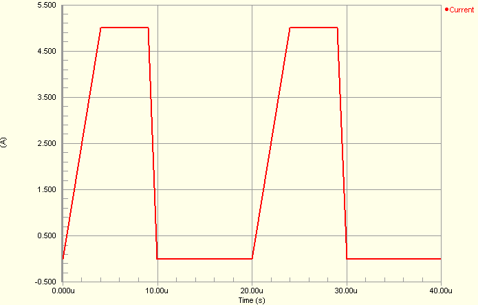
- The shape of the waveform is described as follows:
I(t0) = IIV
 I(tTD) = IIV
 I(tTD + tRT) = IPV
 I(tTD + tRT + tPW) = IPV
 I(tTD + tRT + tPW + tFT) = IIV
 I(tSTOP) = IIV
where,
tis an instance of timeIIVis the initial value of the currentIPVis the pulsed value of the currenttTDis the Time DelaytRTis the Rise TimetPWis the Pulse Width andtFTis the Fall Time
- The value for the current at intermediate values of time is calculated using linear interpolation.
- The simulation-ready pulse current source component (
IPULSE) can be found in the Simulation Sources integrated library (\Library\Simulation\Simulation Sources.IntLib).
Examples
Consider the pulse current source in the above image, with the following characteristics:
- Pin1 (positive) is connected to net
GND - Pin2 (negative) is connected to net
CP - Designator is
ICP - Pulsed Value =
5m - Time Delay =
0 - Rise Time =
1u - Pulse Width =
500u - Period =
1000u - All other parameters for the model are left at their default values.
The entry in the SPICE netlist would be:
*Schematic Netlist:
 ICP 0 CP DC 0 PULSE(0 5m 0 1u 1u 500u 1000u) AC 1 0