Improved OpenBus Documents
Signal Harness Interfaces for Components
In Altium Designer Winter 09, the use of signal harnesses was extended to FPGA and Core projects. The OpenBus system has taken advantage of this in order to reduce the complexity of the interface exported from OpenBus system documents.
OpenBus components now export a signal harness interface to higher level sheets. The following steps outline how to use this new feature.
1. Create the OpenBus System Document
Create a new OpenBus system document by placing components from the OpenBus Palette. Configure and wire the components as necessary. For more information on creating OpenBus designs, please see OpenBus System Design - Basics.
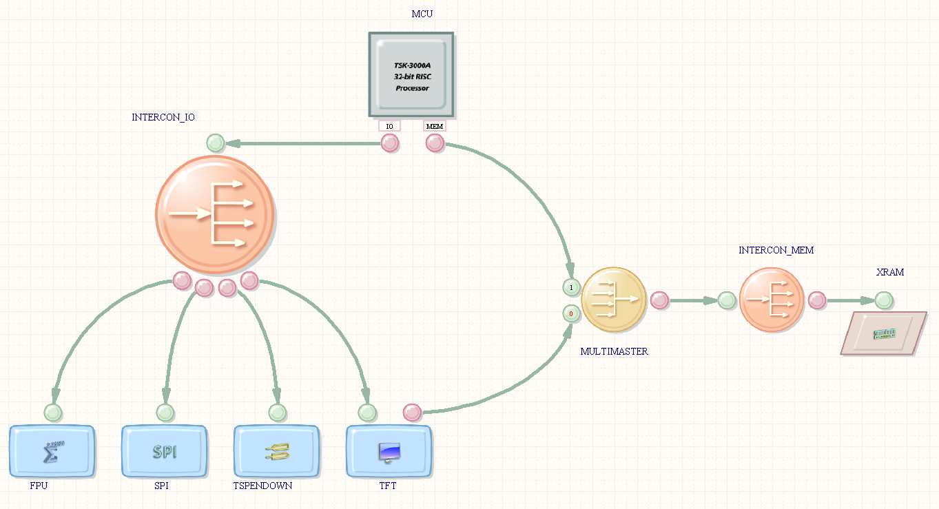
Figure 1. Creating the OpenBus system document
2. Create the Sheet Symbol for the OpenBus Document
A sheet symbol needs to be created for the OpenBus System Document in the higher level Schematic sheet. To do this, right click on the Schematic sheet and choose the Sheet Actions » Create Sheet Symbol from Sheet or HDL command. Select the OpenBus system document in the resulting dialog. This will automatically create the sheet symbol for the OpenBus document, which can be interactively placed.
You will notice the sheet symbol will not contain numerous sheet entries, but rather a handful of sheet entries with harness types. These appear as blue sheet entries. Furthermore, these sheet entries will be grouped by component.
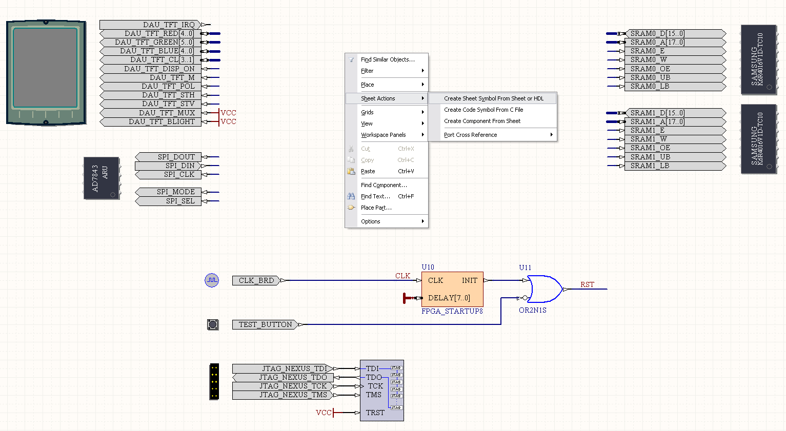
Figure 2. Creating a sheet symbol for the OpenBus system document
3. Create Harness Connectors to Connect Sheet Entries to Port-Plugin Components
The OpenBus system will automatically create harness definitions for the harness sheet entries. A harness connector needs to be created in order to expand the harness sheet entry into its individual signals so that it can be connected to port-plugin components.
A convenient way to place a harness connector corresponding to the harness type of the sheet entry is to right click on the sheet entry and choose the Sheet Entry Actions » Place Harness Connector of Type XYZ command. This will create the harness connector, which can then be interactively placed.
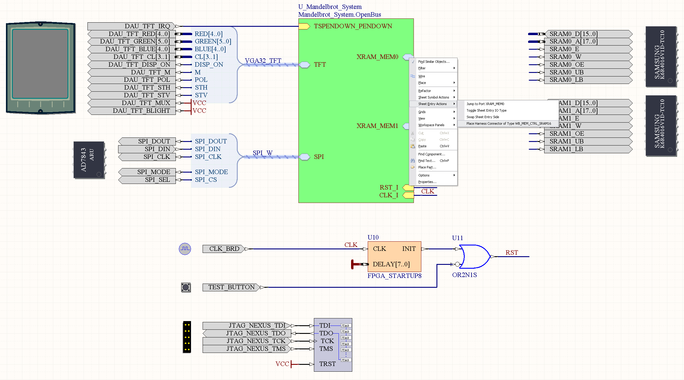
Figure 3. Placing the harness connectors
Tip: Copying Harness Entry Spacing from Port-Plugin Components
The harness entries in the harness definitions generated by the OpenBus system have been ordered to match the order of pins in port-plugin components. However, there may be spaces between pins whereas there are no spaces between the harness entries of the harness connector.
When placing or moving a harness connector, the spacing between the harness entries can be made to match the spacing between the pins by hovering the harness connector over the port-plugin component (ensuring that the cursor is above the port-plugin component) and then pressing the Insert key.

Figure 4. Copying the spacing between pins of port-plugin components to harness entries
FAQ
Can I use the new signal harness features in projects created before Altium Designer Winter 09?
Old OpenBus documents created before Altium Designer Winter 09 will not have this signal harness feature. A pin interface will always be exported to higher level sheets. The OpenBus components in these old documents will need to be replaced with new ones from the OpenBus palette.
What if I don't want to use signal harnesses in my project?
Instead of exporting a signal harness interface for an OpenBus component, the individual pins of the component can instead be exported. This was the behavior in previous Altium Designer releases. If an OpenBus component should export a pin interface, double click on the component to invoke the configuration dialog. Find the Interface Type property and change this to Pins. This property can also be edited via the OpenBus Inspector.
Figure 5. Changing the Interface Type for the OpenBus component
Harness entries do not have directions, so where can I find the directions of the pins?
To view the directions of the pins connected to these harness entries, go to Tools » OpenBus Signal Manager » External connection summary tab. This tab shows the interface which is exported for the OpenBus component and the directions of the component's pins.
The OpenBus Signal Manager is also accessible via a button Manage Signals at the bottom left hand corner of the configuration dialog for OpenBus components.
Figure 6. Using the OpenBus Signal Manager to view the directions of pins for OpenBus components
The synchronize ports to sheet entries tool is not updating the harness type of the sheet entry.
When a sheet entry or port is connected to a harness connector, it will automatically be forced to assume the harness type of the connector. The harness type of the sheet entry cannot be edited in the Sheet Entry Properties dialog. Hence when replacing an existing sheet entry during synchronization, ensure that the sheet entry is not connected to any harness connectors.