SCH Library
Contents
Parent page: Panels

Interactively browse, view and edit Schematic Library components, their pins, and links to models and supplier data.
Summary
The SCH Library panel enables you to peruse through, and make changes to, the components stored in the active schematic library document. The panel also offers the ability to pass on any changes made to components in the library directly to the schematic design document, and also to define model linking for a component.
Panel Access
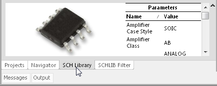
The SCH Library panel will automatically open when a Schematic library is the made active document in the editor. Otherwise, when a SCH Library is the active document in the editor, the SCH Library panel can be accessed by clicking the SCH button at the bottom-right of Altium Designer, and select the SCH Library entry from the pop-up menu:
Panels can be configured to be floating in the editor space or docked to sides of the screen. If the SCH Library panel is currently in the group of docked Workspace panels on the left, use the SCH Library tab located at the bottom of the panels to bring it to the front.
Library Browsing
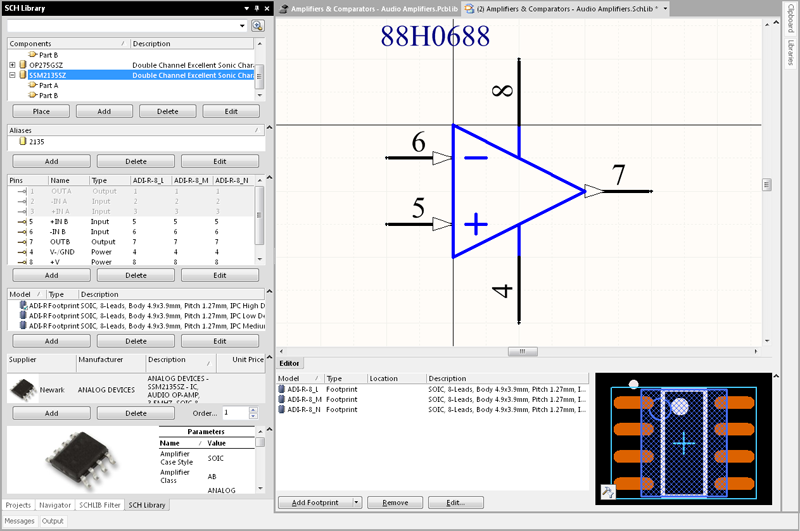
The body of the SCH Library panel has five sections, each offering a different scope of the component parameters in the active SCH Library:
- Components - The list of all components in the active library document. The associated description for each component is also listed, where one exists.
- Aliases - Single definitions that associate various component names that represent variations of the same component type.
- Pins - A list of all the pins that have been placed and defined for the active component.
- Model - All footprint models that are currently linked to the active component.
- Supplier - Definable links to live component data and pricing from parts suppliers.
As you click on a component entry in the list, it will become the active part in the design editor window. The corresponding sections of the design editor will populate with the following information:
- Symbol Editor section - graphical symbol for the component.
- Model section - linked model information.
Both sections of the design editor window are editable, allowing you to change the symbol for the component and add, edit or remove linked models for the component as required. Selecting a Pin object in the panel causes the corresponding graphical object to be highlighted (and zoomed) in the editor workspace. In this way the PCB Library panel offers a fast and easy way to browse, view and access SCH library components and pins.
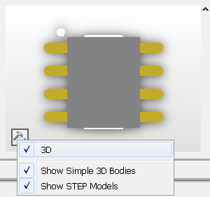
The Model section of the editor window provides a preview image of the component's linked PCB Footprint, if defined. Use the preview's ![]() button to switch the image between 2D and 3D view modes or to select 3D model types.
button to switch the image between 2D and 3D view modes or to select 3D model types.
Filtering Content
The contents of the Components list can be filtered, enabling you to quickly find a particular component within the library. This is especially useful if the library contains a large number of items. Filtering can be applied using one of the following two methods:
Indirect Filtering
This method uses the field at the top of the panel to filter the contents of the list. The name masking is applied based on the entry in the field. Only those components in the list targeted by the scope of the entry will remain displayed.
The filtering feature is not case sensitive and supports 'type-ahead' functionality, meaning that the content of the Components list is filtered as you type.
Use the * wild card operator for more elaborate filtering. For example, typing AD* will display only component footprints whose names begin with AD. Or as in the image below, typing *773 will display only component footprints where the body of the name contains 733.
Direct Filtering
This method is available for all list regions in the panel and allows you to quickly jump to an entry by directly typing within the area of the list. Masking is not applied, leaving the full content of the list visible at all times.
To use the feature for quickly finding a component footprint, click inside the Components section of the panel and type the first letter of the component footprint you wish to jump to. For example, if you wanted to quickly jump to component entries starting with the letter A, you would press that letter on the keyboard. The first component in the list starting with A would be made active.
If there are multiple components starting with the same letter and especially if the library is particularly large, type further letters to target the specific entry you require - for example; AD9 as illustrated by image below which highlights the first of the AD9 series in the list.
Combination Filtering
In some situations it may be helpful to use Indirect and Direct filtering together. If for example, you recall that the component you want to locate has a sub-type variant of BRMZ and a prefix of AD74, this information can be used as Indirect (Mask) and Direct entries respectively, as shown in the image below.
Panel sections
Components list
As you click on a entry in the Components list, it will become the active part inr the design editor window and for the four buttons directly beneath the list. These buttons provide the following commands that can be used with respect to the list of components:
- Place - place the active component onto a schematic design document. When clicked, the schematic document that is used will depend on whether or not any schematic documents are currently open:
- If there are no schematic documents open, clicking the button will cause a new schematic document to be created and made the active document in the design editor window. The active library component will appear floating on the cursor, ready for placement.
- If one or more schematic documents are currently open, the last document to have been active (irrespective of the project it belongs to) will be made the active document in the design editor window and the active library component will appear floating on the cursor, ready for placement.
- Add - add a new component to the library document. The New Component Name dialog will appear. Enter the required name for the new component and this will be added to the list, and a blank sheet will be opened in the design editor window ready for you to define the component.
- Delete - permanently delete the selected component(s) from the library document. A confirmation dialog will appear asking for verification of whether or not to proceed with the deletion
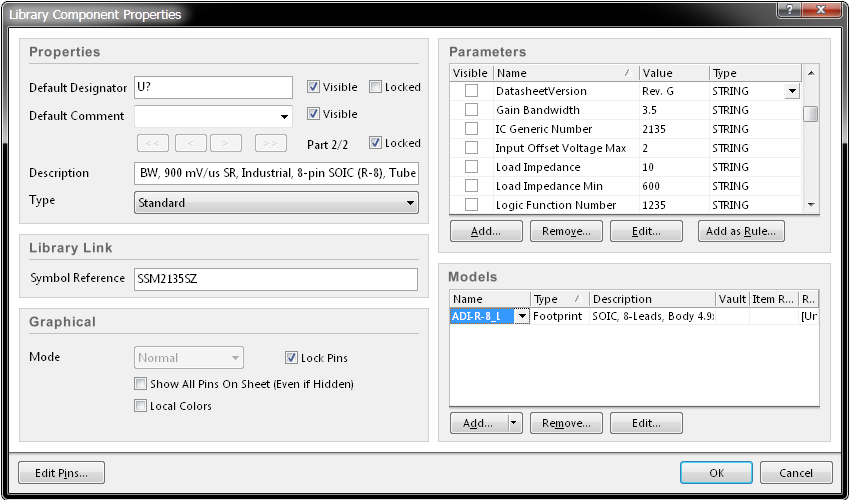
- Edit - open the Library Component Properties dialog, from where you can view/edit properties associated with the active component. The dialog also provides access for creating links to new models or editing existing ones. Double-clicking on a Component entry will also open the Library Component Properties dialog.
Aliases list
The Aliases section of the panel enables you to define component aliases. Using aliases allows you to define a single component entry in the library and associate various component names that represent the same component, but are maybe from a different manufacturer or technology family. For example, you may have a component defined in the main list with the name SSM2135. Aliases may then have been associated to this component with the names SSM2135Z, SSM2135S and SSM2135SZ.
To create a new alias, select the main component definition in the Components section of the panel and press the Add button beneath the Aliases list. The New Component Alias dialog will appear, from where you can enter the required name for the aliased component.
Double-clicking on an entry in the list, or selecting the entry and clicking the Edit button below the list, will open the Change Component Alias dialog, from where you can modify the name for the alias as required.
To delete an alias, select it in the list and click the Delete button below the list.
Pins list
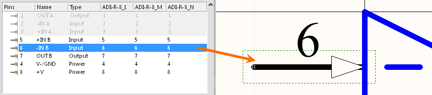
The Pin List section of the panel lists all of the pins that have been placed and defined for the active component. Each entry in the list contains the pin number, any name that has been defined for the pin, its electrical type and, where models have been linked to the component, the corresponding pin in the model that this pin maps to.
As you click on an entry in the list, the corresponding pin graphic will be centered and selected in the Symbol Editor section of the design editor window.
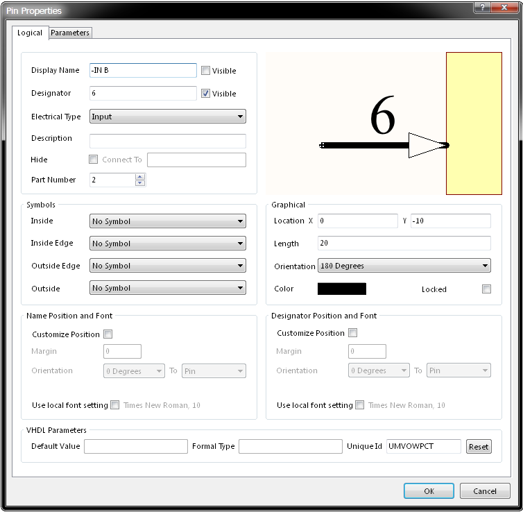
Double-clicking on an entry in the list, or selecting the entry and clicking the Edit button below the list, will open the Pin Properties dialog, from where you can view/modify the properties of the pin as required.
To add a new pin from the panel, click the Add button beneath the list. The pin will appear floating on the cursor within the design editor window. Position the pin as required and click to effect placement. Continue placing additional pins or right-click or press ESC to exit pin placement mode.
To delete one or more pins, select the required entries in the list and press the Delete button. The pins will be removed from the list and deleted from the symbol's graphic.
Models list
The Model section of the panel lists all models that are currently linked to the active component. For each model link the name of the model, its associated type and any description is listed. You can add any number of new model links or edit/remove existing ones.
Click the Add button to open the Add New Model dialog and the subsequent PCB Model dialog, where you browse to select a new footprint model from the available libraries to link to. Double-clicking an entry in the list, or selecting the entry and clicking the Edit button below the list, will open the corresponding model dialog associated with that model type, from where you can edit the underlying model definition.
To delete one or more model links, select the required entries in the list and press the Delete button.
Supplier list
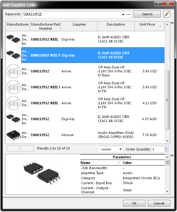
The Suppliers section of the panel lists the physical components from a range of part suppliers that are linked to the currently selected component. Each listed supplier link provides full details of the part including the vendor, manufacturer, part number, description and pricing. The window beneath the list shows a representative part image and its detailed parameters.
You can remove the selected link entry by clicking the Delete button. Click the Add button to open the Add Supplier Links dialog, where a keyword entry is used to search all current suppliers for a suitable match.
Changing the Panel Display
The Components section of the panel is always displayed, however the subsequent panel sections can be set to be displayed or hidden.
This is achieved using the associated button located to the right of a panel section:
- When a section is currently displayed, the button will appear as - which will hide the section when clicked.
- When a section is currently hidden, the button will appear as - which will display the section when clicked.
- When multiple consecutive section are hidden, the button will appear as . Clicking the button will pop-up a menu allowing you to choose which section you wish to display again.
Right-Click Menus
Right-clicking on an entry in the Components list will pop-up a menu of commands.
The commands are as follows:
- Select all - quickly select all component entries in the list.
- Update Schematic Sheets - pass on all changes made to components within the active library document to all open schematic design documents. All instances of changed components that exist on the design documents will be updated.
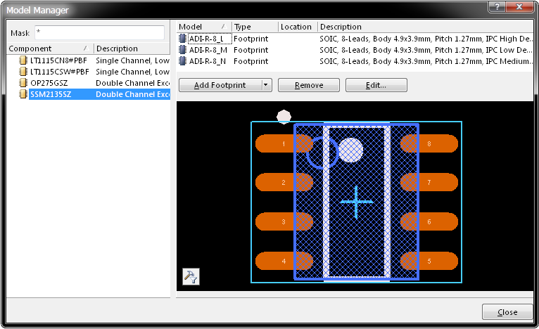
- Model Manager - access the Model Manager dialog, from where you can add, edit or remove models with respect to any of the components contained in the active library, all from one convenient location.
- Copy - place a copy of the selected component(s) onto the Schematic Library Editor's internal clipboard
- Cut - place a copy of the selected component(s) onto the Schematic Library Editor's internal clipboard and then permanently delete the component(s) from the library. A confirmation dialog will appear asking for verification to proceed with the deletion
- Paste - paste a component from the Schematic Library Editor's internal clipboard into the active library document
- Delete - permanently delete the selected component(s) from the library document. A confirmation dialog will appear asking for verification of whether or not to proceed with the deletion.
Notes
- Standard CTRL + Click and SHIFT + Click functionality is supported for selection of multiple entries in a list.
- The active component is that which its symbol and corresponding model information is currently displayed in the design editor window. A component can be active without necessarily being selected in the Components list.
- CTRL + Click over a selected entry in a list to deselect it.
- The keyboard shortcuts Up Arrow, HOME, END and Down Arrow, can be used to display the previous, first, last and next entry in a list region, respectively.
- Multi-part components appear in the list with a
+symbol (expandable) next to them. Each part is listed as a sub-entry below. - In sections of the panel where multiple columns of data exist, the data may be sorted by any column by clicking on the header for that column. Clicking once will sort in ascending order. Click again to sort by descending order.
- You can change the order in which columns of data are displayed. To move a column, click on its header and drag it horizontally to the required position. A valid position is indicated by the appearance of two green positional arrows.
- The component that you paste into the active library document can originate from either a schematic design document or another schematic library document.
- If multiple components have been copied to the clipboard from the main design in the Schematic Editor, all components in the selection will be pasted into the library document.
- If the same component is pasted into the library more than once, or if more than one new component is added to the library without renaming, the copies are distinguished by the suffix _1, _2, _3, and so on.
- A schematic design document must be open in order to pass on changes made to components in the library document.
- For a multi-part component, the corresponding pins for the active part will be highlighted with a white background in the Pin List section of the panel. All pins of other parts will be lowlighted with a grey background. You are, however, still able to edit the pins of these non-active parts.
- As you select pins in the design editor window, the corresponding pin entries will be selected in the panel.
- The attributes of pins and other graphical objects used to define the component can be edited using the SCHLIB Inspector panel. Objects must be selected first in order for the panel to display the attributes.
- When a new schematic library document is created the panel will, by default, contain a single, blank component - Component_1.