SCH Inspector
Contents
- Summary
- Panel Access
- Defining Panel Display Scope
- Inspecting Object Attributes
- Kind
- Design
- Graphical
- Object Specific
- Parameters
- Editing Object Attributes
- Editing Attributes with Numeric Values
- Modification Using an Expression
- Batch Replacement of String-based Attributes
- Smart Editing of String-based Attributes
- Batch Replace Tab
- Formula Tab
- Editing/Adding Parameters
- Notes
Parent page: Panels

Manually select Schematic objects or use the SCH Filter Panel to populate the SCH Inspector panel with objects to be viewed or edited.
Summary
The SCH Inspector panel enables you to interrogate and edit the properties of one or more design objects in the active schematic document (or all open schematic documents). Used in conjunction with appropriate filtering, the panel can be used to make changes to multiple objects of the same kind, from one convenient location.
Panel Access
To display the SCH Inspector panel, ensure that a schematic is the active document in the editor and click the SCH button at the bottom-right of Altium Designer, and select the SCH Inspector entry from the pop-up menu.
Panels can be configured to be floating in the editor space or docked to sides of the screen. If the SCH Inspector panel is currently in the group of docked Workspace panels on the left, use the SCH Inspector tab located at the bottom of the panels to bring it to the front.
Defining Panel Display Scope
You may have a large quantity of objects selected in the editor workspace that are of differing types. Out of all such objects, you may wish to edit the properties of certain object types only, without losing or having to alter your selection. This can be achieved using the underlined controls at the top of the panel, to essentially define a 'display scope' for the panel:
![]()
The left-hand underlined control allows you to set the type of objects that can be displayed. Clicking on the control will reveal a selection pop-up.
Use the pop-up to choose which object types you wish to include in the panel for display and editing - either all objects or specific objects. To choose one or more specific object types, enable the Display only option and then enable the check box next to the required object(s) in the list beneath. The list will only contain those object types currently selected in the main workspace.
![]()
When enabling specific object types for display, the control will reflect the choice by listing the enabled types, separated by commas.
Click on the right-hand underlined control (shown above as 'current document') to choose from the following options:
- current document - only display target objects from the active schematic document in the design editor window
- all open documents - display target objects from all open schematic documents, irrespective of the parent project they belong to
- open documents of the same project - display target objects from all open schematic documents that are source documents of the same parent project
Note: With respect to the last two options for this control, schematic documents that are open, but hidden, will not be considered when displaying objects.
Inspecting Object Attributes
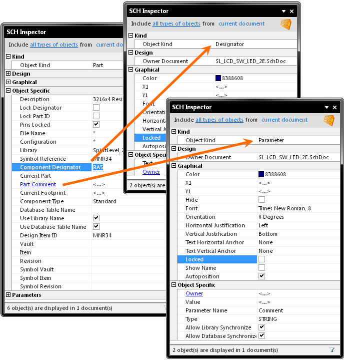
Clicking on a single object in the design editor window will select the object and display attributes associated to it in the SCH Inspector panel. Information is displayed under the following common collapsible sections:
Kind
This section of the panel contains one entry only, relating to the kind of design object that is being 'inspected'. For example, clicking on a component will display the entry 'Part', while clicking on a component designator will display the entry 'Designator', and so on.
Design
This section of the panel also contains one entry only, relating to the owner document upon which the object has been placed.
Graphical
This section of the panel contains graphical attributes of the selected object. Attributes here may include the location of the object, its orientation and colors used in its display.
Object Specific
This section of the panel contains attributes specific to the object being inspected and which are not graphical attributes.For example, selecting a component will display the following attributes that are specific to a component:
- Description
- Lock Designator
- Lock Part ID
- Pins Locked
- File Name
- Configuration
- Library
- Library Reference
- Component Designator
- Current Part
- Part Comment
- Current Footprint
- Component Type
Other selected objects will have different attributes displayed. For example, selecting a port object will display attributes including Name and IO Type.
Parameters
For an object to which parameters can be 'attached', this section allows Parameters to be inspected, added and deleted for single or multiple objects.
Editing Object Attributes
You can edit attributes of a selected object, by editing the relevant entry in the panel. The change will take effect once you click outside of the field you are editing. This is one of the advantages of using the panel to edit object properties - the panel will remain open, allowing you to change attribute after attribute, as needed, without having to close and reopen a properties dialog each time.
If the object you are inspecting has child objects associated with it, they will appear in blue in the Object Specific section (rather like a hyperlink). Click on these entries to display the attributes pertaining specifically to these child objects. For each child object, an link will be available back to the parent object - the 'Owner' link in the Object Specific section of the panel.
Another advantage of using the panel for editing is that you can modify multiple objects from the one place without having to edit, through dialogs, one object at a time. Selected objects can be of the same or differing type. Those attributes that are common to all objects in the selection will be displayed in the panel. Common attributes that have differing values between objects will be displayed as <...>. Edit the attributes as required - the changes made will be conveyed instantly to each object in the selection.
By using filtering, you can apply a query (an expression for the filter) to target a specific group of objects in the design and then use the SCH Inspector panel to edit the attributes for these multiple objects, directly.
Editing Attributes with Numeric Values
For a numerical-based attribute of a selected object, the simplest modification to that attribute's value is made by typing a new value to replace the existing one. The plus and minus operators can be used to specify the value's sign. A value entered without a specified sign is assumed to be positive. Therefore entering 20 is the same as entering +20.
You can enter specific units of measurement for a value entered. The software will convert the value into the current units defined for the document. If no units are specified, the default units set for the document will be used.
Modification Using an Expression
More advanced modification can be achieved by using an arithmetic expression. Simply select the entry for the attribute you wish to modify and type the expression that will be used to modify its value. You can enter any arithmetic expression, using any built-in arithmetic operators and functions (found in Pascal).
If you wish to use the current value for the attribute as part of the expression, you will need to make reference to this original value, either by using the full name of the attribute, or by using the exclamation character (the supported substitute for the name of the attribute currently being modified). If you wish, you may use any other attribute field name in an expression. When using attribute names, any spaces in the names must be replaced by the underscore character.
To illustrate an example of using a simple expression, consider a component pin that has a Length attribute currently set to 30. If you wanted to extend this length to 45, you could enter the expression:
Length + 15
...or, in shortened form:
! + 15
Note that the spaces are optional. When you press ENTER, the value will be updated to 45.
If instead you want to shorten the pin to a length of 20, you could use the subtraction operator, as illustrated by the following expressions:
Length - 10
! - 10
To illustrate use of a function, the previous expression could be re-written as:
! - sqrt(100)
the result would be the same - a length of 20.
By using the attribute's name, or substitution character (!), the previous expressions add to or subtract from the current value for the attribute. Without such entries in the expression, you would be setting the attribute's value to the evaluated result of the expression. For example, if the attribute name or substitution character had been left out of the previous expressions, the resulting pin length would have been 15 and -10 respectively.
Again, you can enter specific units of measurement for a value entered into an expression. The software will convert the value into the current units defined for the document. If no units are specified, the default units set for the document will be used. By selecting multiple objects in the workspace, you can change numerical attributes simultaneously using an expression. For example, you may want to adjust the length of a series of component pins, or shift components vertically or horizontally by a specific distance.
Batch Replacement of String-based Attributes
There are times when you may want to modify a string-based attribute that is common to multiple selected objects in the workspace. For example you may wish to rename selected data bus net label objects from D1, D2, D3, etc, to Data1, Data2, Data3, etc. To perform this type of batch replacement, the use of string substitution syntax is supported in the panel.
A string substitution entry is enclosed in braces and has the form:{oldstring=newstring}
An entry of this form causes all occurrences of oldstring found in the attribute's value to be replaced with newstring. In the case of the data bus net labels, you would enter {D=Data} in the value field for the Text attribute.
Should you wish to replace multiple, differing string portions in the same target string, type multiple substitution entries, each enclosed in its own set of curly braces. For example, consider the following net labels, associated to the output wiring of a WB_PRTIO component, configured to have four, 8-bit I/O ports:
XPort8A_Out[7..0]
XPort8B_Out[7..0]
XPort8C_Out[7..0]
XPort8D_Out[7..0]
Now consider having placed a second WB_PRTIO component, configured to have four, 32-bit I/O ports. Instead of placing individual net labels of a similar fashion on each output wire of each port in this second device, you could select all four of the above net labels, copy them, paste them onto the corresponding wires of the new port device and then rename them. It is in this last operation that batch string substitution comes into play.
If the intended format of the new net labels is to be YPort32x_Out[31..0], where x represents the port (A, B, C or D), then you could select the four net labels, access the SCH Inspector panel and enter the following into the value field for the Text attribute:
{X=Y}{8=32}{7=31}
The software takes this entry and effectively performs a batch substitution - substituting for the first expression, then the second, and so on.
Smart Editing of String-based Attributes
The SCH Inspector panel offers further support for string modification through its Smart Edit feature. Simply click on a shared attribute of the selected objects, whose value is a string. A ![]() button will become available at the far right of the cell. Click on this button to access the Smart Edit dialog.
button will become available at the far right of the cell. Click on this button to access the Smart Edit dialog.

The dialog offers two methods for performing string modification, accessed from the Batch Replace and Formula tabs respectively.
Batch Replace Tab
This tab in the Smart Editor dialog provides simple straightforward substitution, along the lines of the string substitution discussed previously (but without having to enter the curly braces). Click inside the From field and enter the portion of the current string that you wish to replace. Then click inside the To field and enter the string to be used as the replacement. The familiar string substitution syntax is displayed at the bottom of the tab.
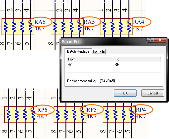
For example, consider several component designators that have the prefix RA but you need to change them to have prefix RP instead. In this case, select the components, click on the Component Designator attribute in the panel and access the Smart Edit dialog. Then on the Batch Replace tab, enter RA in the From field and RP in the To field (the replacement string is therefore {RA=RP}). Note that just entering A and B in the From/To fields is equivalent, as the P character is unchanged.
After clicking OK, the component designators on the schematic will be modified accordingly.
As with basic string substitution, the Batch Replace tab provides for replacement of multiple, differing string portions in the same target string.
Enter the various substitutions as distinct From-To entries. Consider the previous WB_PRTIO example (see Batch Replacement of String-Based Attributes, above), where strings of the form XPort8x_Out[7..0] need to be changed to YPort32x_Out[31..0]. In this case, you would enter three distinct substitution entries on the Batch Replace tab, as shown here.
Formula Tab
This tab provides for more advanced modification, allowing you to apply a specific expression to the selected string objects. The expression can include any built-in arithmetic operators and functions that apply to strings (found in Pascal). Once again, if you wish to use the current value for the attribute as part of the expression, you will need to make reference to this original value, either by using the full name of the attribute, or by using the exclamation character (the supported substitute for the name of the attribute currently being modified). When using attribute names, any spaces in the names must be replaced by the underscore character. So, for example, use of the Pin Designator field within a formula should be entered as Pin_Designator.
Consider for example three selected memory components specified in a design, with designators U1, U3 and U5. You might want to extend the designators of these components by including some indication of their role. Using the addition operator, you could write an expression to add to the existing string value of the Component Designator attribute. This would take the existing (original) string value and concatenate it with a specified new string, as illustrated below:
Component_Designator + '_MEM'
...or, in shortened form:
! + '_MEM'
Note that the spaces are optional. When you press ENTER, the designators of the components will be updated to U1_MEM, U3_MEM and U5_MEM respectively.
To illustrate the use of string-based functions consider the Copy function, which can be used to take a portion of an original string and place it within an expression to create a new string. Take again the WB_PRTIO example (see Batch Replacement of String-Based Attributes), where strings of the form XPort8x_Out[7..0] need to be changed to YPort32x_Out[31..0]. In this case you could select the four net labels, access the Smart Edit dialog for the Text attribute and write the following expression on the Formula tab:
'Y' + Copy(Text,2,4) + '32' + Copy(Text,7,6) + '31..0]'
...or, in shortened form:
'Y' + Copy(!,2,4) + '32' + Copy(!,7,6) + '31..0]'
Editing/Adding Parameters
For an object to which parameters can be 'attached', an additional section is displayed in the SCH Inspector panel - Parameters.
For a single selected object, this section lists all of the parameters currently defined for that object. For multiple selected objects, the section displays only those parameters that are common to all objects in the selection. The following objects can have parameters associated to them:
- Part
- Pin
- Port
- Sheet Symbol
- Parameter Set
- Net Class Directive
- PCB Layout Directive
- Probe Directive
- Stimulus Directive
- Test Vector Index Directive
Click on the hyperlink for a parameter name to display and edit the properties for that parameter directly from within the panel. Click on the 'Owner' link to go back to editing the parent object to which the parameter belongs.
You can add any number of user-defined parameters from within this section of the panel. With respect to components, this allows you to define anything from component ratings, to stock information, to purchasing data, or revision history.
Simply enter the value for the new parameter in the field to the right of the Add User Parameter entry. When you press Enter or click out of the field, the Add new parameter to n object(s) dialog will appear, where n represents the number of selected design objects to which this new parameter will be simultaneously added.
Change the name for the new parameter as required and click OK - the parameter will be added to the list of parameters for the selected object(s).
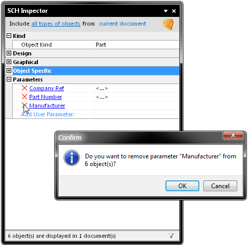
To remove a parameter from the selected object(s), click on the red cross symbol to the immediate left of the parameter name. A dialog will appear prompting for confirmation to proceed with the deletion.
Notes
- Pressing the F11 key will toggle the visibility of the panel in the workspace.
- Information will only appear in the panel when either:
1) One or more objects have been selected in the design editor window or;
2) Object entries are selected in the SCH Filter panel. - If you have defined the display scope for the panel to display specific object types, this scope will remain when the selection is cleared in the main workspace. If you subsequently select an object that is not part of this previously defined scope, the panel will display a control at its center - 'Click here to display all objects' - which, when clicked will reset the Include portion of the display scope to all types of objects.
- With multiple parts selected in the workspace, you can drill-down to make changes to Designator, Comment or Parameters and the changes will be made to all parts in the selection. Similarly, when editing multiple sheet symbol objects, you can drill-down to modify the attributes of child objects (Sheet Filename, Sheet Name, Parameters) and the changes will be applied to all sheet symbols in the selection.
- You can use the Up Arrow and DOWNARROW keys to pass up and down the list of attributes in the panel respectively.
- When applying a filter using the SCH Filter panel, the attributes for the resulting filtered objects will only be displayed in the SCH Inspector panel if the Select option - located in the Objects passing the filter area of the panel - is enabled prior to application of the filter.