Text String
Parent page: Objects

A placed Text String.
Summary
A text string (also referred to as an annotation) is a non-electrical drawing primitive. It is a single line of free text that can be placed on a schematic sheet. Uses might include section headings, revision history, timing information or some other descriptive or instructive text.
Availability
Text strings are available for placement in both Schematic and Schematic Library Editors by:
- Choosing Place » Text String [P, T] from the respective editor's main menus.
- Clicking the button on the Utility Tools drop-down () of the Utilities toolbar.
Placement
After launching the command, the cursor will change to a cross-hair and you will enter text string placement mode. A text string will appear "floating" on the cursor.
- Position the object and click or press Enter to effect placement.
- Continue placing further text strings, or right-click or press Esc to exit placement mode.
Additional actions that can be performed during placement are:
- Press the Tab key to access an associated properties dialog, from where properties for the text string can be changed on-the-fly.
- Press the Alt key to constrain the direction of movement to the horizontal or vertical axis, depending on the initial direction of movement.
- Press the Spacebar to rotate the text string anti-clockwise or Shift+Spacebar for clockwise rotation. Rotation is in steps of 90°.
- Press the X or Y keys to mirror the text string along the X-axis or Y-axis respectively.
Non-Graphical Editing...
The following methods of non-graphical editing are available:
...via an Associated Properties Dialog
This method of editing uses the following dialog to modify the properties of a text string object.
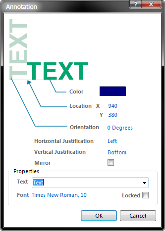
The Annotation dialog.
The Annotation dialog can be accessed prior to entering placement mode, from the Schematic – Default Primitives page of the Preferences dialog. This allows the default properties for the text string object to be changed, which will be applied when placing subsequent text strings.
During placement, the dialog can be accessed by pressing the Tab key.
After placement, the dialog can be accessed in one of the following ways:
- Double-clicking on the placed text string object.
- Placing the cursor over the text string object, right-clicking and choosing Properties from the context menu.
- Using the Edit » Change command and clicking once over the placed text string object.
...via an Inspector Panel
An Inspector panel enables the designer to interrogate and edit the properties of one or more design objects in the active document. Used in conjunction with appropriate filtering, the panel can be used to make changes to multiple objects of the same kind, from one convenient location.
...via a List Panel
A List panel allows the designer to display design objects from one or more documents in tabular format, enabling quick inspection and modification of object attributes. Used in conjunction with appropriate filtering, it enables the display of just those objects falling under the scope of the active filter – allowing the designer to target and edit multiple design objects with greater accuracy and efficiency.
Graphical Editing
This method of editing allows you to select a placed text string object directly in the workspace and change its location graphically. Text strings can only be adjusted with respect to their size by changing the size of the font used (accessed through the Annotation dialog). As such, editing handles are not available when the text string object is selected:
A selected Text String.
- Click anywhere inside the dashed box and drag to reposition the text string as required. While dragging, the text string can be rotated (Spacebar/Shift+Spacebar) or mirrored (X or Y keys to mirror along the X-axis or Y-axis respectively).
- The text for a text string object can be edited in-place by:
- Single-clicking the text string to select it.
- Single-clicking again (or pressing the Enter key) to enter the in-place editing mode. Sufficient time between each click should be given to ensure the software does not interpret the two single-clicks as one double-click (which would open the text string's properties dialog).
- To finish editing in-place text, press the Enter key, or use the mouse to click away from the text string.
Special Strings
While text string objects can be used to place user-defined text on a schematic sheet, it's not just user-defined text that can be placed. To assist in producing documentation, the concept of "special strings" is used. These act as placeholders for design or system information that is to be displayed on the Schematic at the time of output generation.
Default sets of predefined special strings are provided for use with new schematic documents. But the designer can also add their own custom special strings by defining additional parameters at the document-level (for use on current schematic only) or project-level (available for use across all schematic sheets and PCB documents in the project).
Placing a Special String
To use a special string on a schematic, simply place a text string object and set its text to be one of the special string names.
On a schematic sheet, special strings are characterized by the prefix '=' (e.g. =CurrentTime, =CurrentDate, etc). The list of available special strings – both predefined and custom – can be seen by clicking the drop-down arrow associated to the Text field, in the Annotation dialog.
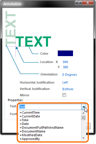
Accessing special strings for a placed text string object.
Revealing Special Strings in the Workspace
The values of some special strings can only be viewed when the relevant output is generated. Most special strings can be viewed directly on-screen however, by enabling the Convert Special Strings option, on the Schematic – Graphical Editing page of the Preferences dialog.
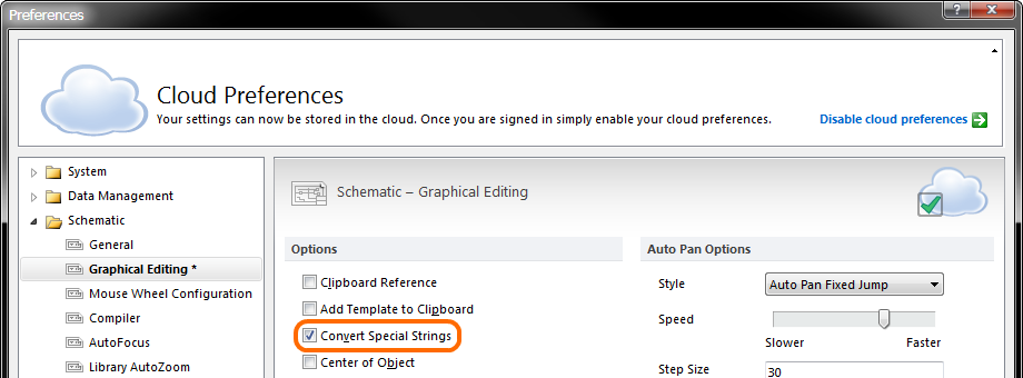
Enabling the Convert Special Strings option allows the data for certain special strings to be viewed in the workspace, prior to output generation.
Schematic Predefined Special Strings
The following are the predefined special strings available for use on a schematic document. The majority of these link to default parameter information defined for the active document on the Parameters tab of the Document Options dialog (Design » Document Options).
=Address1– displays the value specified for the default document-level parameterAddress1.=Address2– displays the value specified for the default document-level parameterAddress2.=Address3– displays the value specified for the default document-level parameterAddress3.=Address4– displays the value specified for the default document-level parameterAddress4.=ApprovedBy– displays the value specified for the default document-level parameterApprovedBy.=Author– displays the value specified for the default document-level parameterAuthor.=CheckedBy– displays the value specified for the default document-level parameterCheckedBy.=CompanyName– displays the value specified for the default document-level parameterCompanyName.=CurrentDate– the current date, automatically calculated from the user's system settings and in the formatdd/mm/yyyy, updated upon editing the schematic or on refresh/redraw. Example:10/12/2012.=CurrentTime– the current time, automatically calculated from the user's system settings and in the formath:mm:ss AM/PM, updated upon editing the schematic or on refresh/redraw. Example:2:39:47 PM.=Date– used to display static date information. Displays the value specified for the default document-level parameterDate. Unlike the=CurrentDatespecial string, which is automatically calculated and presented in a set format, the user can enter static date information in any format they like.=DocumentFullPathAndName– used to display the full path and name of the document into which the string is placed. Example:C:\MyTestDesign\PSU.SchDoc.=DocumentName– used to display the schematic's file name only (without the file path). Example:PSU.SchDoc.=DocumentNumber– displays the value specified for the default document-level parameterDocumentNumber. The source parameter can also be updated through the Sheet Numbering For Project dialog, when using the Tools » Number Schematic Sheets command.=DrawnBy– displays the value specified for the default document-level parameterDrawnBy.=Engineer– displays the value specified for the default document-level parameterEngineer.=ImagePath– displays the value specified for the default document-level parameterImagePath.=ModifiedDate– the modified date stamp of the schematic, automatically populated. Example:10/12/2012.=Organization– displays the value specified for the default document-level parameter Organization.=ProjectName– displays the actual name of the project (including extension). For example, for a project with filenameMyPCB.PrjPcb, this special string will displayMyPCB.PrjPcb.=Revision– displays the value specified for the default document-level parameterRevision.=Rule– displays the value specified for the default document-level parameterRule. The value for this parameter will initially beUndefined Rule(appearing as*on the schematic). Double-click on the parameter value to access the ability to define a rule type and edit its constraint(s).=SheetNumber– the sheet number of the current schematic. This value is calculated when using the following commands from the Tools menu:
a) Number Schematic Sheets – the assigned sheet number, in the Sheet Numbering For Project dialog, will be entered into the value for the default document-level parameter SheetNumber. The special string, when used on the Editor tab view of the schematic sheet will source its information from here.
b) Annotate Compiled Sheets – the assigned compiled sheet number, in the Annotate Compiled Sheets dialog, will be displayed when viewing the string on the Compiled tab view of the schematic. The option to display the expanded compiled names of the Sheet Number object must be enabled, in the Compiled Names Expansion section, on the Schematic – Compiler page of the Preferences dialog.
=SheetTotal– the sheet total for the project. This value is calculated when using the following commands from the Tools menu:
a) Number Schematic Sheets – the sheet total, in the Sheet Numbering For Project dialog, will be entered into the value for the default document-level parameter SheetTotal. The special string, when used on the Editor tab view of the schematic sheet will source its information from here.
b) Annotate Compiled Sheets – the sheet total, source from the number of sheets listed in the Annotate Compiled Sheets dialog, will be displayed when viewing the string on the Compiled tab view of the schematic. The option to display the expanded compiled names of the Sheet Number object must be enabled, in the Compiled Names Expansion section, on the Schematic – Compiler page of the Preferences dialog.
=Time– used to display static time information. Displays the value specified for the default document-level parameterTime. Unlike the=CurrentTimespecial string, which is automatically calculated and presented in a set format, the user can enter static time information in any format they like.=Title– displays the value specified for the default document-level parameterTitle.=VersionControl_RevNumber– the current revision number of the document. Version control must be used for this string to contain any information.
Special Strings for use with Component Parameters
Several additional special strings (or special interpretations of existing ones) are available when defining component parameters. In each case, the special string is entered as the value for a parameter.
=CurrentFootprint– displays the name of the currently assigned footprint for the component, as defined in the Models region of the associated Component Properties dialog.=Comment– displays the value appearing in the component's Comment field, as defined in the Properties region of the associated Component Properties dialog.=Description– displays the value appearing in the component's Description field, as defined in the Properties region of the associated Component Properties dialog.=[ParameterName]– displays the value defined for a specified component parameter. Enter the actual name of a component parameter as the special string name – so for a component parameter namedPowerRating, simply enter=PowerRating. When defining the Comment property for a component, the associated drop-down field will be populated with special strings for all existing component parameters – enabling quick use of any defined parameter's value for the Comment.
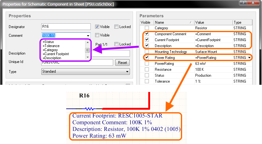
The use of special strings with component parameters.