Sheet Symbol
Contents
- Summary
- Availability
- Placement
- Non-Graphical Editing
- ...via an Associated Properties Dialog
- ...via an Inspector Panel
- ...via a List Panel
- Graphical Editing
- Sheet Symbol Actions
- Opening a Selected Sheet Symbol's Sub-Sheet
- Creating a Schematic Sheet directly from a Sheet Symbol
- Creating a VHDL File directly from a Sheet Symbol
- Creating a Verilog File directly from a Sheet Symbol
- Renaming a Sheet Symbol's Child Sheet
- Example
- Synchronizing Sheet Entries and Ports
- Synchronization for Current Sheet Symbol
- Synchronization for all Sheet Symbols
- Using the Dialog
- Flipping Selected Sheet Symbols along the X-Axis
- Flipping Selected Sheet Symbols along the Y-Axis
- Toggling Sheet Entry IO Type in a Selected Sheet Symbol
- Notes
Parent page: Objects

Sheet Symbol.
Summary
A sheet symbol is an electrical design primitive. It is used to represent a sub-sheet in a multi-sheet hierarchical design. Sheet symbols include sheet entry symbols, which provide a connection point for signals between the parent and child sheets, similar to the way that Ports provide connections between sheets in a flat-sheet design.
Availability
Sheet symbols are available for placement in the Schematic Editor only. Use one of the following methods to access the placement command:
- choose Place » Sheet Symbol [P, S] from the main menus
- click the button on the Wiring toolbar.
Placement
After launching the command, the cursor will change to a cross-hair and you will enter sheet symbol placement mode. Placement is made by performing the following sequence of actions:
- click or press Enter to anchor the top-left corner of the sheet symbol
- move the cursor to adjust the size of the sheet symbol, then click or press Enter to anchor the diagonally-opposite corner and thereby complete placement of the sheet symbol.
Continue to place other sheet symbols, or right-click or press Esc to exit placement mode.
Non-Graphical Editing
The following methods of non-graphical editing are available:
...via an Associated Properties Dialog
This method of editing uses the following dialog to modify the properties of a Sheet Symbol object.
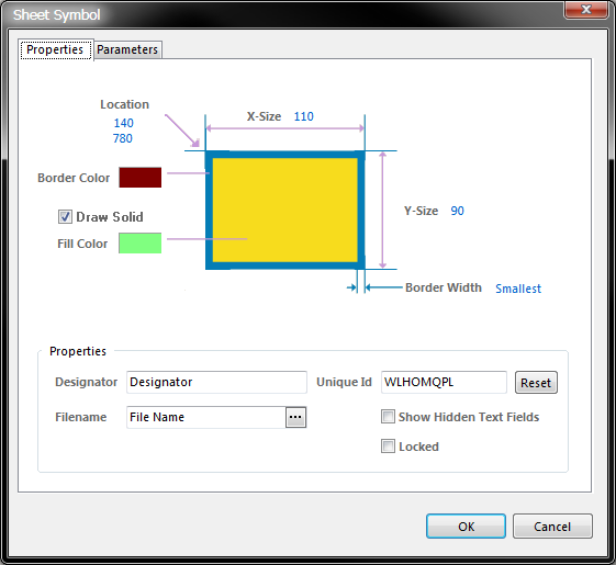
The Sheet Symbol dialog.
The Sheet Symbol dialog can be accessed prior to entering placement mode, from the Schematic - Default Primitives page of the Preferences dialog (Tools » Schematic Preferences). This allows you to change the default properties for the sheet symbol object, which will be applied when placing subsequent sheet symbols.
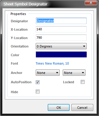
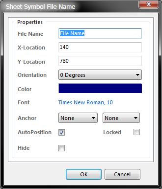
The Sheet Symbol Designator dialog and Sheet Symbol File Name dialog.
During placement, the Sheet Symbol dialog can be accessed by pressing the Tab key.
After placement, the Sheet Symbol dialog can be accessed in one of the following ways:
- double-clicking on the placed sheet symbol object
- selecting the sheet symbol object and choosing Properties from the right-click pop-up menu
- choosing the Change command from the Edit menu and then clicking once over the placed sheet symbol object.
The sheet symbol Designator and Filename text fields can be formatted independently of the sheet symbol itself. The corresponding properties dialogs for each - the Sheet Symbol Designator and Sheet Symbol File Name dialogs respectively - can be accessed using the three methods described above (replacing sheet symbol with the relevant object whose properties you wish to view/modify).
...via an Inspector Panel
An Inspector panel enables the designer to interrogate and edit the properties of one or more design objects in the active document. Used in conjunction with appropriate filtering, the panel can be used to make changes to multiple objects of the same kind, from one convenient location.
...via a List Panel
A List panel allows the designer to display design objects from one or more documents in tabular format, enabling quick inspection and modification of object attributes. Used in conjunction with appropriate filtering, it enables the display of just those objects falling under the scope of the active filter – allowing the designer to target and edit multiple design objects with greater accuracy and efficiency.
Graphical Editing
This method of editing allows you to select a placed sheet symbol object directly in the workspace and change its size, shape or location, graphically.
When a sheet symbol object is selected, the following editing handles are available:
- Click and drag A to resize the sheet symbol in the vertical and horizontal directions separately.
- Click and drag B to resize the sheet symbol in the vertical and horizontal directions simultaneously.
- Resizing the sheet symbol will not affect the absolute positions of any defined sheet entries within.
- Click anywhere on the sheet symbol - away from editing handles - and drag to reposition it.
- The sheet symbol's Designator and Filename text fields can only be adjusted with respect to their size by changing the size of the font used (accessed through the Sheet Symbol Designator and Sheet Symbol File Name dialogs, respectively). As such, editing handles are not available when either of these objects are selected:
- Click anywhere inside the dashed box and drag to reposition the text object as required. The object can be rotated or flipped while dragging:
- Press the Spacebar to rotate the text. Rotation is anti-clockwise and in steps of 90°.
- Press the X or Y keys to flip the text along the X-axis or Y-axis respectively.
If the Enable In-Place Editing option is enabled on the Schematic - General page of the Preferences dialog (Tools » Schematic Preferences), you will be able to edit the name for the Designator or File Name directly in the workspace. Select the text object and then click once to invoke the feature. Type the new name as required and then click away from the text object or press Enter to effect the change.
Sheet Symbol Actions
Right-clicking over a placed sheet symbol will pop-up a context-sensitive menu, from which a variety of commands are available that act on that sheet symbol (or on all selected sheet symbols where applicable). The following sections detail each of these commands.
Opening a Selected Sheet Symbol's Sub-Sheet
This command applies only to the sheet symbol under the cursor and is accessed by right-clicking and choosing Sheet Symbol Actions » Open SubSheet "SheetName.SchDoc" from the menu that appears.
The child sheet for the symbol will be opened (if not already) and made the active document in the main design window.
Creating a Schematic Sheet directly from a Sheet Symbol
This command is used to create a new schematic document from a sheet symbol and add ports to that document corresponding to each of the sheet entries on the symbol. In this way, you can automatically create the sub-sheets for a multi-sheet schematic design, based on the sheet symbols you have created and placed on the top sheet.
The command can be accessed either by:
- choosing Design » Create Sheet From Symbol from the main menus. You will be prompted to choose a sheet symbol
- right-clicking over the required sheet symbol and choosing Sheet Symbol Actions » Create Sheet From Symbol from the menu that appears.
After launching the command (and choosing the sheet symbol if applicable), a dialog will appear asking whether you wish to reverse input/output directions. This option changes the electrical type for a port on the newly created sheet to be the opposite of that for the corresponding sheet entry that it represents. Choose Yes or No as required - the schematic document will be created and opened as the active document. The matching ports for the sheet entries on the symbol will be located in the bottom left-hand corner of the new document.
The schematic document that is created is named using the entry in the sheet symbol's Filename field. You can either enter the intended name for the document in this field before launching the command, complete with extension (i.e. DocumentName.SchDoc), or leave the name blank and enter the name when saving the generated document at a later stage.
Creating a VHDL File directly from a Sheet Symbol
This command is used to create a new VHDL document (*.Vhd) from a placed sheet symbol on the current schematic document.
The command can be accessed either by:
- choosing Design » Create HDL File From Symbol » Create VHDL File From Symbol from the main menus. You will be prompted to choose a sheet symbol
- right-clicking over the required sheet symbol and choosing Sheet Symbol Actions » Create VHDL File From Symbol from the menu that appears.
After launching the command (and choosing the sheet symbol if applicable), the VHDL document will be created and opened as the active document. The sheet entries on the symbol will be included as declared ports in the document's entity definition.
The template for the architecture will be defined, but the component and signal declarations are left ready for you to code in.
The VHDL document is named using the entry in the sheet symbol's Filename field. This entry is also used as the name for the document's entity.
The VHDL document is named using the entry in the sheet symbol's Filename field.
Creating a Verilog File directly from a Sheet Symbol
This command is used to create a new Verilog document (*.V) from a placed sheet symbol on the current schematic document.
The command can be accessed either by:
- choosing Design » Create HDL File From Symbol » Create Verilog File From Symbol from the main menus. You will be prompted to choose a sheet symbol
- right-clicking over the required sheet symbol and choosing Sheet Symbol Actions » Create Verilog File From Symbol from the menu that appears.
After launching the command (and choosing the sheet symbol if applicable), the Verilog document will be created and opened as the active document. The sheet entries on the symbol will be included in the document's module definition.
The Verilog document is named using the entry in the sheet symbol's Filename field. This entry is also used as the name for the document's module.
The Verilog document is named using the entry in the sheet symbol's Filename field.
Renaming a Sheet Symbol's Child Sheet
This command provides a quick and efficient facility for renaming the child schematic sheet referenced by a selected sheet symbol.
The command can be accessed either by:
- choosing Design » Rename Child Sheet from the main menus. You will be prompted to choose a sheet symbol
- right-clicking over the required sheet symbol and choosing Sheet Symbol Actions » Rename Child Sheet from the menu that appears.
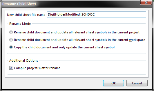
After launching the command (and choosing the sheet symbol if applicable), the Rename Child Sheet dialog will appear.
Initially, the New child sheet file name field will contain the current name for the document. Type the new name for the document as required - ensuring that the .SCHDOC extension remains.
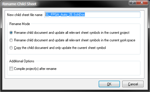
The Rename Child Sheet dialog.
The Rename Mode region of the dialog allows you to determine how the renaming should proceed. The first two options, as their names suggest, rename the child sheet.
The options differ in the scope of the update with respect to the sheet symbols that point to this sheet - either in the active project or across all projects in the active design workspace. In each case, the Filename field for the sheet symbol will be updated to reflect the newly named child sheet.
The third option takes a copy of the child sheet before renaming the original. Only the current sheet symbol is updated using this option. This is useful when the current child sheet is referenced by multiple sheet symbols, and one sheet symbol needs to reference a modified version of the circuitry contained on that sheet. You still want to keep the original sheet - you are creating a renamed copy of this sheet with which to point to from a single sheet symbol. You can then modify the content of the sheet as required.
Enabling the Compile project(s) after rename option will ensure that the newly named child sheet is correctly inserted into the design hierarchy, which will be reflected on the Projects panel.
Example
Consider the three sheet symbols in the adjacent image, each one pointing to the DigitHolder.SchDoc sub-sheet.
Consider now that the middle symbol is required to point to a slightly modified version of the underlying schematic. The canvas for the modified sheet can be quickly generated and this sheet symbol made to point to it, by using the Rename Child Sheet feature, and selecting the third option - to copy the original sheet and update only the current sheet symbol.
After defining the required rename options, clicking OK will proceed with the rename, updating the sheet symbol's Filename field to point to the newly named document.
The Rename Child Sheet dialog.
As can be seen in the image and the image below, the original schematic document has not been deleted and the other sheet symbols still point to it. The copy of the original document- renamed to DigitHolder(Modified).SchDoc - is referenced only by the intended sheet symbol. The Projects panel is updated to reflect the two child sheets that are accessed by sheet symbols on the parent sheet.
Synchronizing Sheet Entries and Ports
The Schematic Editor provides a facility for maintaining synchronization between the sheet entries on a sheet symbol and the corresponding ports on the referenced child sheet below. Two commands are used to implement this facility, differing only in their scope.
Synchronization for Current Sheet Symbol
Allows you to synchronize the sheet entries and sub-sheet ports for the sheet symbol currently under the cursor. The command can be accessed by right-clicking over the required sheet symbol and choosing Sheet Symbol Actions » Update ports and sheet entries on the chosen sheet symbol from the menu that appears.
After launching the command, the Synchronize Ports To Sheet Entries On SheetSymbolDesignator dialog will appear:
This incarnation of the Synchronize dialog includes a single tab for the sheet symbol under the cursor.
Synchronization for all Sheet Symbols
Allows you to synchronize the sheet entries and sub-sheet ports for each sheet symbol in the active design project. The command can be accessed by choosing Design » Synchronize Sheet Entries And Ports from the main menus.
After launching the command, the Synchronize Ports To Sheet Entries In ActiveProjectName dialog will appear:
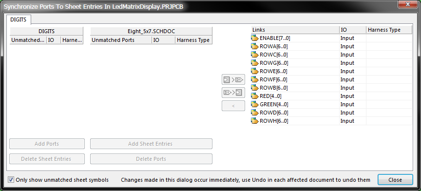
The Synchronize Ports To Sheet Entries Dialog.
This incarnation of the Synchronize dialog includes a separate tab for each sheet symbol found in the project. The ordering of the tabs depends on the order in which documents have been added to the project and the order in which sheet symbols were added to each document.
Using the Dialog
The aim, when using the Synchronize dialog, is to ensure that all sheet entries on a sheet symbol are matched to ports on the referenced child sheet both in terms of name and I/O Type. The left-hand side of the dialog provides two regions:
- one listing all currently unmatched sheet entries associated to the chosen sheet symbol. The Designator of the sheet symbol appears as the header for the region. Each sheet entry in this region is listed in terms of its Designator and I/O Type
- one listing all currently unmatched ports on the schematic sheet referenced by the sheet symbol. The document name appears as the header for the region. Each port entry in this region is listed in terms of its Name and I/O Type.
The right-hand side of the dialog lists all currently linked (or matched) sheet entry-port pairings. Each entry shows the common name used by both the sheet entry as its Designator and the port as its Name. The IO column shows the current I/O Type set for each pairing. Both name and I/O Type can be modified from this dialog - click on the required field entry and enter the new name/choose the required I/O Type. Any modification will be passed immediately to both the sheet entry and port.
The simplest way to explain the workings of the dialog, in terms of matching sheet entries with ports, is to use an underlying example. Consider the sheet symbol and corresponding ports in the image to the right.
Each sheet entry in the symbol corresponds, both in name and I/O Type, to a port in the referenced schematic sub-sheet. Accessing the Synchronize dialog for this sheet symbol, there are no unmatched entries.
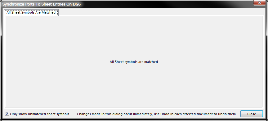
The Synchronize Ports To Sheet Entries dialog.
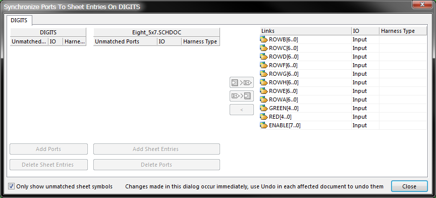
Now consider the same sheet symbol, but with a few intentional changes made within the design, as listed below and summarized in the following image:
- sheet entry designator changed to G[4..0]
- sheet entry designator changed to R[4..0] and I/O Type changed to Output
- extra sheet entry added, with designator B and I/O Type Input
- sheet entry for ENABLE removed
- port name changed to GR[4..0]
This time when the Synchronize dialog is accessed, the changes introduced cause links between sheet entries and ports to be broken and the unmatched lists become populated.
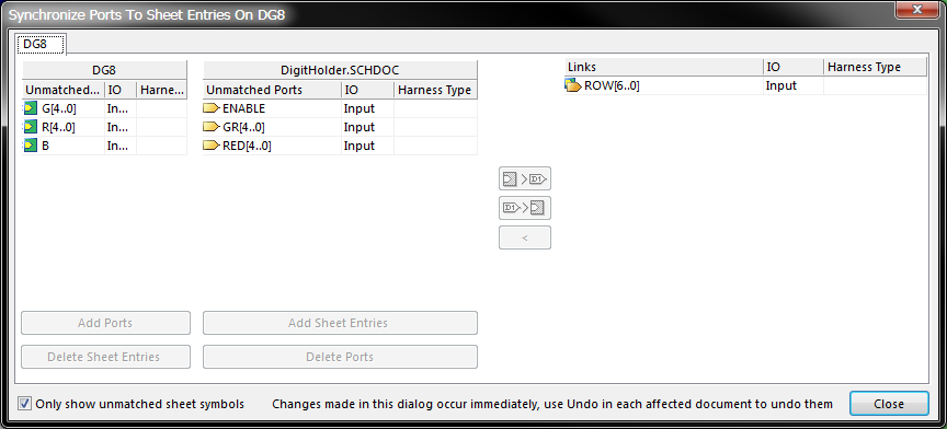
The Synchronize Ports To Sheet Entries dialog.
The two unmatched regions must now be used to resolve the current unsynchronized state that exists between the sheet entries of the symbol and the ports of the sub-sheet. Below each region are two buttons, the use of which will involve making one or more of the following matching decisions:
- If there are sheet entries that you no longer require, select each (use Ctrl+click, Shift+click or click-and-drag for multi-select) and click the Delete Sheet Entries button. Each sheet entry in the selection will be removed from the sheet symbol.
- If there are ports that you no longer require, select each and click the Delete Ports button. Each port in the selection will be removed from the child sheet.
- If there are existing sheet entries that you need to keep but no corresponding ports for these entries, you can automatically create ports with the same names and I/O Types by selecting each sheet entry and clicking the Add Ports button. You will be taken to the child sheet, with the port(s) floating on the cursor ready for initial placement. Click or press Enter to place the port(s). The Synchronize dialog will reappear, with an entry for each sheet entry-port pairing automatically entered into the Links region of the dialog.
- If there are existing ports that you need to keep but no corresponding sheet entries for these ports, you can automatically create sheet entries with the same names and I/O Types by selecting each port and clicking the Add Sheet Entries button. You will be taken to the sheet symbol, with the sheet entry(ies) floating on the cursor ready for initial placement. Click or press Enter to place the sheet entry(ies). The Synchronize dialog will reappear, with an entry for each sheet entry-port pairing automatically entered into the Links region of the dialog.
All other residual unmatched entries will either be due to name or I/O Type mismatching. For these, manual matching can be carried out. This is done by selecting a sheet entry in one region and a port in the other and then using one of the following two buttons to determine which name and I/O Type attributes are used when linking:
|
| Use this button to link the selected sheet entry with the selected port, using the name and I/O Type defined for the sheet entry. The port will be renamed and/or its I/O type changed. |
|
| Use this button to link the selected sheet entry with the selected port, using the name and I/O Type defined for the port. The sheet entry will be renamed and/or its I/O type changed. |
If the name or I/O Type is not as you require, remember that these can be changed from the Synchronize dialog, after the unmatched entries have been linked.
If you want to break up a linked entry, select it in the Links region of the dialog and click on the ![]() button.
button.
The actual process of matching will vary from sheet symbol to sheet symbol, depending on the discrepancies involved and your preferred matching techniques. Considering the point reached with the underlying example:
the sheet entries and ports could be quite easily matched and re-synchronized back to their original states by performing the following actions:
- Selecting the entry for port ENABLE and clicking the Add Sheet Entries button
- Selecting the entry for sheet entry B and clicking the Delete Sheet Entries button
- Selecting the entries for sheet entry R[4..0] and port RED[4..0] and clicking the button
- Selecting the entries for sheet entry G[4..0] and port GR[4..0] and clicking the button This keeps the I/O Type setting of Input, as required. Then, once linked, change the name to GREEN[4..0] in the Links region of the dialog
The approach to matching is not set in stone - the tools are provided to allow you to match as quickly and as efficiently as possible. For example, the first two actions in the list above could be achieved by a single, alternative action to select the entries for sheet entry B and port ENABLE and click on the ![]() button.
button.
Flipping Selected Sheet Symbols along the X-Axis
This command allows you to flip selected sheet symbols along the X-axis.
The command can be accessed either by:
- selecting the required symbols and choosing Edit » Move » Flip Selected Sheet Symbols Along X from the main menus
- right-clicking over the required sheet symbol (or a symbol in a selected group of symbols) and choosing Sheet Symbol Actions » Flip Selected Sheet Symbols Along X from the menu that appears.
After launching the command the selected sheet symbols will be flipped. The sheet entries associated with a symbol will essentially be swapped to the opposite side of the symbol (in the horizontal plane) - those on the left will be repositioned on the right and vice-versa.
Flipping Selected Sheet Symbols along the Y-Axis
This command allows you to flip selected sheet symbols along the Y-axis.
The command can be accessed either by:
- selecting the required symbols and choosing Edit » Move » Flip Selected Sheet Symbols Along Y from the main menus
- right-clicking over the required sheet symbol (or a symbol in a selected group of symbols) and choosing Sheet Symbol Actions » Flip Selected Sheet Symbols Along Y from the menu that appears.
After launching the command the selected sheet symbols will be flipped. The sheet entries associated with a symbol will essentially be swapped to the opposite side of the symbol (in the vertical plane) - those at the top will be repositioned at the bottom and vice-versa.
Toggling Sheet Entry IO Type in a Selected Sheet Symbol
This command allows you to toggle the I/O Type for all sheet entries in all selected sheet symbols, simultaneously.
The command can be accessed either by:
- selecting the required symbols and choosing Edit » Move » Toggle All Sheet Entries IO Type In Selected Sheet Symbol from the main menus
- right-clicking over the required sheet symbol (or a symbol in a selected group of symbols) and choosing Sheet Symbol Actions » Toggle All Sheet Entries IO Type In Selected Sheet Symbol from the menu that appears.
After launching the command, the I/O Type defined for each sheet entry will be toggled, where applicable.
The actual change depends on the current I/O Type as follows:
- Unspecified remains Unspecified
- Output changes to Input
- Input changes to Output
- Bidirectional remains Bidirectional.
Notes
By using sheet symbol instantiation, multiple channels on the same sub-sheet can be referenced from a single sheet symbol. The syntax used involves the use of the Repeat keyword in the sheet symbol's Designator field and takes the form:
Repeat(SheetSymbolDesignator, FirstInstance, LastInstance), where SheetSymbolDesignator is the base name for the sheet symbol and FirstInstance and LastInstance together define the number of channels to be instantiated. The FirstInstance parameter must start at a value of one (1) onwards. The following example image illustrates the use of the Repeat keyword to instantiate 8 input channels for an audio mixer.
When the project is built, the Compiler instantiates the channel the required number of times as it builds the internal compiled model, using a chosen annotation scheme to uniquely identify each component in each channel. The channel sub-sheet is not duplicated. Instead, once compiled, a Compiled Document Tabs appear at the bottom of the sub-sheet document in the main design window for each channel on that sheet, as shown in the example image below.
The Compiled Document Tabs.
Multiple sub-sheets may be referenced by a single sheet symbol. Separate each filename by a semi-colon in the Filename field. With the effective use of off-sheet connectors placed on the sub-sheets, you can effectively spread a section of your design over multiple sheets, treated as though they were one giant (flat) sheet. Note however, that use of off-sheet connectors is only possible for sheets referenced by the same sheet symbol.