Port
Parent page: Objects
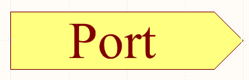
A placed Port.
Summary
A port is an electrical design primitive. It is used to make an electrical connection between one schematic sheet and another, in a design using multiple sheets. The name of the port defines the connection (i.e. a port on a schematic sheet connects to ports with the same name on other sheets in the project).
Availability
Ports are available for placement in the Schematic Editor only. Use one of the following methods to access a placement command:
- Choose Place » Port [P, R] from the main menus.
- Click the
 button on the Wiring toolbar.
Placement
After launching the command, the cursor will change to a cross-hair and you will enter port placement mode. Placement is made by performing the following sequence of actions:
- Click or press Enter to anchor the left-hand edge of the port.
- Move the cursor to adjust the length of the port as required, then click or press Enter to complete placement of the port.
- Continue placing further ports or right-click or press Esc to exit placement mode.
Additional actions that can be performed during placement – while the port is still floating on the cursor, and before its left-hand edge is anchored – are:
- Press the Tab key to access an associated properties dialog, from where properties for the port can be changed on-the-fly.
- Press the Alt key to constrain the direction of movement to the horizontal or vertical axis, depending on the initial direction of movement.
- Press the Spacebar to rotate the port anti-clockwise or Shift+Spacebar for clockwise rotation. Rotation is in steps of 90°.
- Press the X or Y keys to mirror the port along the X-axis or Y-axis respectively.
Non-Graphical Editing...
The following methods of non-graphical editing are available:
...via an Associated Properties Dialog
This method of editing uses the following dialog to modify the properties of a port object.

The Port Properties dialog.
The Port Properties dialog can be accessed prior to entering placement mode, from the Schematic – Default Primitives page of the Preferences dialog. This allows the default properties for the port object to be changed, which will be applied when placing subsequent ports.
During placement, the dialog can be accessed by pressing the Tab key.
After placement, the dialog can be accessed in one of the following ways:
- Double-clicking on the placed port object.
- Placing the cursor over the port object, right-clicking and choosing Properties from the context menu.
- Using the Edit » Change command and clicking once over the placed port object.
...via the SCH Inspector Panel
The SCH Inspector panel enables the designer to interrogate and edit the properties of one or more design objects in the active document. Used in conjunction with appropriate filtering, the panel can be used to make changes to multiple objects of the same kind, from one convenient location.
...via the SCH List Panel
The SCH List panel allows the designer to display design objects from one or more documents in tabular format, enabling quick inspection and modification of object attributes. Used in conjunction with appropriate filtering, it enables the display of just those objects falling under the scope of the active filter – allowing the designer to target and edit multiple design objects with greater accuracy and efficiency.
Graphical Editing
This method of editing allows you to select a placed port object directly in the workspace and change its length, height, or location graphically.
When a port object is selected, the following editing handles are available:
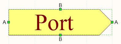
A selected Port.
- Click and drag A to change the length of the port.
- Click and drag B to change the height of the port.
- Click anywhere on the port – away from editing handles – and drag to reposition it. While dragging, the port can be rotated (Spacebar/Shift+Spacebar) or mirrored (X or Y keys to mirror along the X-axis or Y-axis respectively).
- The name for the port object can be edited in-place by:
- Single-clicking the port to select it.
- Single-clicking again (or pressing the Enter key) to enter the in-place editing mode. Sufficient time between each click should be given to ensure the software does not interpret the two single-clicks as one double-click (which would open the port's properties dialog).
- To finish editing in-place text, press the Enter key, or use the mouse to click away from the port.
Autosize
Doing things manually typically means having to expend additional effort. Of course, this gives you full control, but if an automated process can be put in place that is both fast and effective, its use can be of great benefit. With the port object, automation of port size can certainly have a positive impact on productivity.
To take advantage of the autosizing feature, enable the port's Autosize option. This can be done in either the Port Properties dialog, or the SCH Inspector panel.
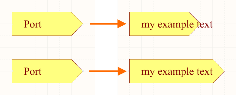
Autosizing in action. With feature disabled (top) the port would have to be manually resized. But when enabled (bottom), the port is automatically resized to accommodate the length of the new text.
And if you change font size, the autosizing feature's got you covered. The height of the port will simply be resized to accommodate the text accordingly.
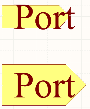
With autosizing enabled (bottom) the port will resize to fit the new text size.
Notes
- All Ports with the same name, within the same or different schematic documents, are considered to be electrically connected.
- The I/O Type option in the Port Properties dialog allows you to define the port's electrical type. Choose from either
Input,Output,BidirectionalorUnspecified. - Should you need to negate (include a bar over the top of) a port name, this can be done in one of two ways:
- Include a backslash character after each character in the name (e.g.
E\N\A\B\L\E\) - Enable the Single '\' Negation option on the Schematic – Graphical Editing page of the Preferences dialog, then include one backslash character at the start of the name (e.g.
\ENABLE).
- Include a backslash character after each character in the name (e.g.
- Port names are not used for naming nets. This means a system-generated net name will be used if no net label or power object is associated with that net.
- By default, the font used for the port's Name follows the global document-level font, set on the Sheet Options tab of the Document Options dialog (Design » Document Options). This can be overridden at the individual port-level, using the control to the right of the Font label, in the Port Properties dialog – allowing you to fully control the textual presentation of ports as needed.