No ERC
Parent page: Objects
Summary
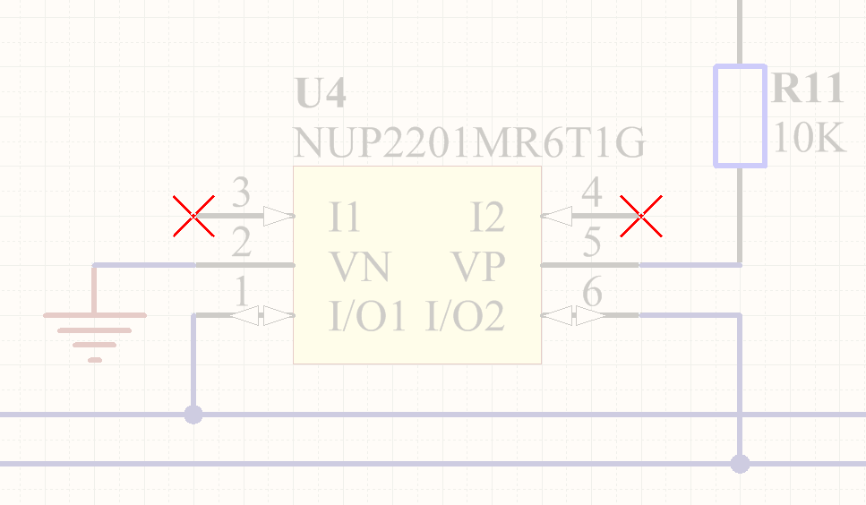
The No ERC object is a design directive. This directive is placed on a node in the circuit to suppress all reported Electrical Rule Check warnings and/or error violation conditions that are detected when the schematic project is compiled. Use this directive to deliberately limit error checking at a certain point in the circuit that you know will generate a warning (such as an unconnected pin), while still performing a comprehensive check of the rest of the circuit.
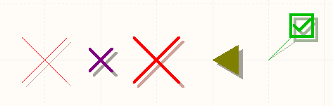
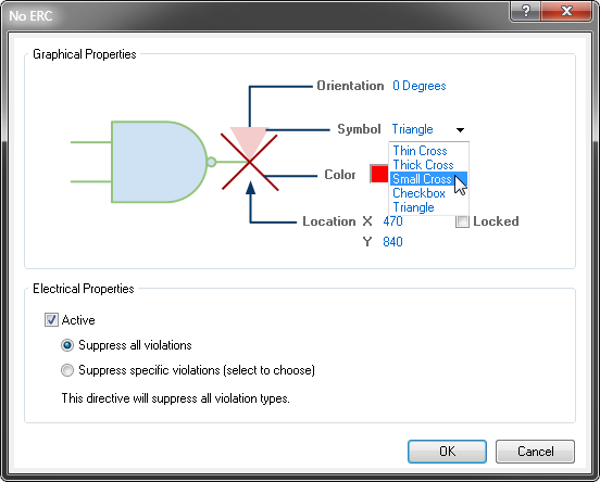
The No ERC directive supports a number of different styles, and can be displayed in any color. Use this ability to reflect the design intent for this point in the circuit.
The No ERC directive has two modes of operation, which can be switched between:
- Suppress All Violations – In this mode all possible warning or error conditions are suppressed.
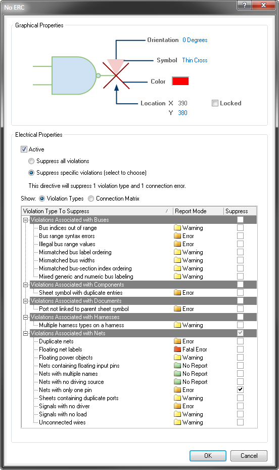
- Suppress Specific Violations – In this mode only the selected warning or error conditions are suppressed, any other warning or error will be detected and reported.
Availability
No ERC design directives are available for placement in the Schematic Editor only. To place a No ERC directive:
- Select Place » Directives » Generic No ERC [P, V, N] from the menus, or click the
 button on the Wiring toolbar, to place a No ERC marker that is pre-configured to target all violations.
 - Select Place » Directives » Specific No ERC [P, V, E] from the menus, or click the button on the Wiring toolbar, to place a No ERC marker that can be configured to target specific violations.
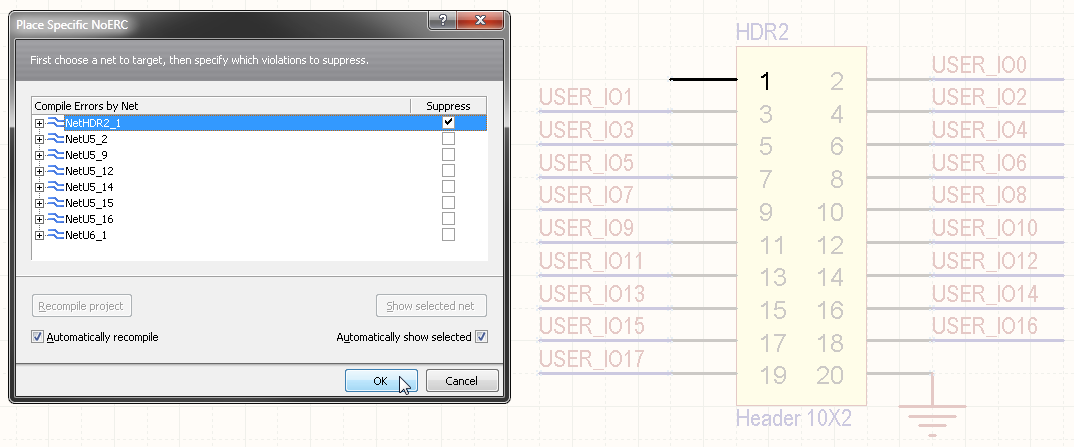
This command will open the Place Specific NoERC dialog, which you can use to help you interactively select and place suitable specific No ERC markers. Use of the dialog is described in detail below.
Placement - Generic No ERC directive
After launching the command, the cursor will change to a cross-hair to indicate placement mode:
- Position the cursor over a wire or other net object, and click or press Enter to place a directive at that point in the circuit.
- Continue placing further No ERC directives, or right-click or press Esc to exit placement mode.
- To rotate the No ERC directive while in placement mode, press the Spacebar to rotate anti-clockwise in 90° steps, Shift+Spacebar to rotate clockwise in 90° steps. Note that this will not have a visual effect on all directive symbols.
Note that pressing the Tab key during placement will access the associated properties dialog, from where properties for the No ERC directive can be changed on-the-fly.
Placement - Specific No ERC directive
A Specific No ERC directive is configured to target a specific violation, so it must be configured to do this. To simplify this process, Altium Designer launches an interactive tool to automatically configure the directive to target the appropriate violation, during placement.
To use this interactive tool:
- Run the Place » Directives » Specific NoERC command and the Place Specific NoERC dialog will open. The dialog will automatically load a list of all violations present on the current schematic sheet
- To be confident that it accurately reflects the violations that currently exist, click the Recompile project button.
- If there are multiple violations detected, the Automatically recompile option should also be enabled, to ensure the list remains accurate as you place directives.
- Click on a violation in the list, the view of the schematic sheet will automatically change to show the violating object. Note that each detected violation can be expanded to show details of the error.
- Click the Suppress checkbox for the error of interest.
- Click OK to close the dialog, a No ERC marker will appear on the cursor, ready for placement on the point in the circuit that is creating the violation.
- Place the directive on the point of violation in the circuit. After clicking to place, the Place Specific NoERC dialog will automatically re-appear, ready to resolve the next specific violation.
- Continue to place directives to resolve all violations on the current schematic sheet, then move to the next sheet in the project. The big advantage of this guided automatic process is that each Directive is automatically configured to only suppress specific errors/warnings.
Right-click placement
An alternative approach to working through the Place Specific NoERC dialog is to selectively place a Specific No ERC directive on a point in the circuit that is already showing a violation, highlighted by a wavy colored line.
To place a specific No ERC marker targeted to that violation, right-click on the violating object (not the wavy colored line) and select the Place NoERC to Suppress command. The No ERC directive will appear on the cursor, pre-configured to suppress this violation. Press Tab to edit the look of the directive before placement.
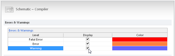
Altium Designer's default settings do not highlight Warnings with a wavy line, this is enabled in the Schematic - Compiler page of the Preferences dialog, as shown in the image below.
Non-Graphical Editing...
The following methods of non-graphical editing are available:
...via the No ERC Properties dialog
To edit the properties during placement, Press the Tab key while the object is floating on the cursor. To edit after placement, use one of the following techniques:
- Double-click on the placed No ERC directive.
- Select the No ERC directive and choosing Properties from the right-click pop-up menu.
- Choose the Edit » Change command and then click once on the placed No ERC directive.
Generic No ERC directive
Note that a directive can be switched from the Generic to Specific type by changing the dialog's Electrical Properties option from Suppress all violations to Suppress specific violations.
Specific NoERC directive
...via the SCH Inspector panel
An Inspector panel enables the designer to interrogate and edit the properties of one or more design objects in the active document. Used in conjunction with appropriate filtering, the panel can be used to make changes to multiple objects of the same kind, from one convenient location. The graphic and specific object properties for a No ERC directive object may be edited in the SCH Inspector panel.
...via the SCH List panel
A List panel allows the designer to display design objects from one or more documents in tabular format, enabling quick inspection and modification of object attributes. Used in conjunction with appropriate filtering, it enables the display of just those objects falling under the scope of the active filter – allowing the designer to target and edit multiple design objects with greater accuracy and efficiency. The properties of a selected No ERC directive are available in the SCH List panel.
...via the NoERC Manager
To review and edit all the No ERC directives used across the entire project, select the command Tools » NoERC Manager from the menus. The NoERC Manager dialog will open:
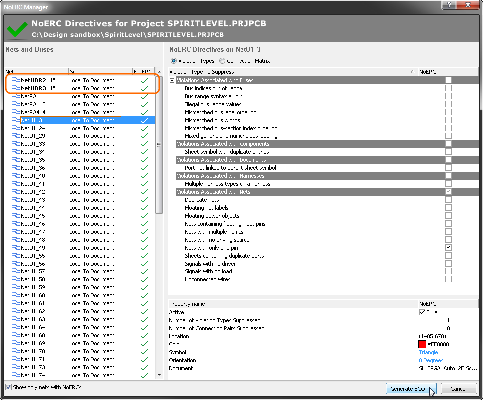
The NoERC Manager dialog allows you to move through the list of nets with directives applied and edit any number of No ERC directives. When editing is complete, click the Generate ECO button to apply all of the changes.
Graphical Editing
Graphical editing capabilities for No ERC directives include:
- Moving – click and hold on a No ERC directive and move it to a new location.
- Rotating – click and hold, then press the Spacebar (or Shift+Spacebar) while moving the directive to rotate it. Note that symmetrical Symbol styles, such as Thin Cross, will not change their appearance when they are rotated.
Controlling the Printing of No ERC Directives
By default, all design directives are included during printing. To control this, disable directives that you do not want included on your printouts in the Schematic Print Properties dialog, as shown below.
This dialog can be accessed via File » Page Setup and choosing one of the following options :
- Click the Advanced button.
- Default Prints, select Schematic Prints in the list then click Configure.
- Print Preview, then right-click in the Preview Schematic Prints dialog and choose Configuration.