Designator
Parent page: Objects

The Designator uniquely identifies each component in the design.
Summary
The designator field is a child parameter object of a schematic component (part). It is used to uniquely identify each placed part, distinguishing it from all other parts placed in all the schematic sheets in the project.
Availability
The designator is automatically placed when the parent component part object is placed. As such, it is not a design object that can be directly placed by the user.
Non-Graphical Editing
There are 2 aspects to consider in relation to editing the designator: editing the value of the designator; and editing the display properties of the designator.
...via the Schematic Library Editor
By default, the designator is not visible in the Schematic Library Editor. It is edited in the Library Component Properties dialog, double-click on the Component name in the SCH Library panel or click the Edit button to open the dialog, as shown in the image below. Typically the designator is only given a suitable prefix followed by a question mark. The question mark is detected by the Schematic Editor's Annotation tool and replaced with a suitable numeric suffix during project annotation.
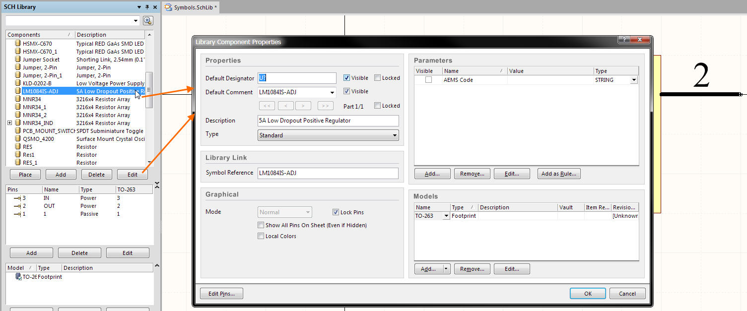
Double click on the component name, or click the Edit button, to open the dialog and defined the value of the Designator string.
Alternatively, the designator (and comment) strings can be displayed in the Schematic Library Editor, and then doubled-clicked on to edit their properties. To display them, select Tools » Document Options to open the Library Editor Workspace dialog, then enable the Always Show Comment/Designator option, as shown in the image below. This setting is a property of the current Schematic Library.
Enable the Always Show Comment/Designator option to display these strings in the Schematic Library Editor.
...via the Schematic Editor
The designator can be defined in the Schematic Editor as the component is being placed, or after the component has been placed on a schematic sheet.
- To edit the designator during component placement, press the Tab key while the component is floating on the cursor. The Properties for Schematic Component dialog will open, enter the required designator string and click OK to close the dialog and complete the component placement. Continue to place components, or press Esc to terminate placement.
- To edit the designator after placement, double-click on the placed component to open the Properties for Schematic Component dialog where the designator can be edited. Click OK to close the dialog and commit the change.
...via the Designator Display Properties Dialog
The appearance of the designator string, which includes the font type, size and color, can be defined as:
- A software default, by setting the Designator defaults in the Schematic - Default Primitives page of the Preferences dialog. This setting will apply unless overridden by settings defined in the component symbol in the Schematic Library Editor.
- A property of the symbol, by setting the properties of the designator in the Parameter Properties dialog in the Schematic Library Editor. This requires the designator string to be made visible, as described in the previous section.
- By editing the component designator string of the placed schematic component - double-click on the comment string to edit the properties, or use the in-place editing technique described below.
All 3 approaches open the Parameter Properties dialog, as shown below. Note that all properties of the designator string can be edited in this dialog.
The value and the appearance of the Designator string can be edited in the Parameter Properties dialog.
...via an Inspector Panel
Both the SCH Inspector and the SCHLIB Inspector panels can also be used to interrogate and edit the properties of the selected comment string. Used in conjunction with appropriate filtering, the panels can be used to make changes to multiple objects of the same kind, from one convenient location.
...via a List Panel
A List panel allows the designer to display design objects from one or more documents in tabular format, enabling quick inspection and modification of object attributes. Used in conjunction with appropriate filtering, it enables the display of just those objects falling under the scope of the active filter – allowing the designer to target and edit multiple design objects with greater accuracy and efficiency.
Fixing the Location of the Designator String
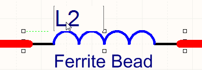
The default behavior of the designator string is to autoposition it as a component is rotated during placement. If this behavior is not required, turn off the Autoposition option in the Parameter Properties dialog (refer to the previous image), either during symbol creation or after the component has been placed on a schematic sheet. Note that doing this sets this parameter to be classified as a manual parameter (meaning manually positioned parameter). Manual Parameters are identified by a dot on the lower left corner of their selection box. Manual parameter marker dots can be hidden by disabling the Mark Manual Parameters option in the Schematic - Graphical Editing page of the Preferences dialog, as shown below.
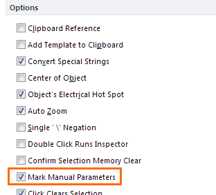
Manually positioned strings are marked by a dot, disable the display of dots in the Preferences dialog.
Graphical Editing
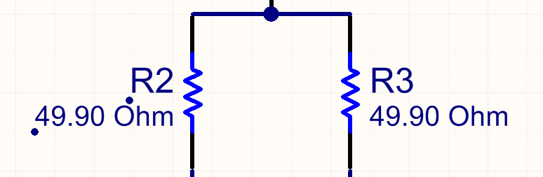
The comment string can be edited graphically, using what is known as in-place editing. To edit a comment string in-place, click once to select, pause for a second, then click a second time to enter edit mode.
 Click once to select the string.
 Pause, then click a second time to enter in-place edit mode.
 Here the string has been selected, ready to type in a replacement string.
The value of the Comment string can be edited in-place.
Once editing is complete, press Enter or click away from the string to exit in-place editing mode.
Notes
- The Schematic Editor includes a simple auto-increment feature for the designator, which can be used during the placement of multiple instances of the same part. To use this, press Tab while the first component is floating on the cursor and enter a suitable designator, for example
R1. Subsequent components will then be designatedR2,R3, etc. Note that when you switch to placing a different component type you must again press Tab and enter a suitable designator prefix. - When placing multi-part components and the initial designator is assigned as just described, a part suffix will automatically be assigned, for example
U3A,U3B,... If the initial designator is not assigned all parts will have the same suffix, this is resolved by the Schematic Editor's Annotation command. The part suffix can be alpha or numeric, use the Alpha Numeric Suffix option in the Schematic - General page of the Preferences dialog to configure this.