Bus
Parent page: Objects

A Bus is a polyline object that is used, in conjunction with other objects, to define the connection of multiple nets.
Summary
A bus is an electrical design primitive. It is a polyline object that represents a multi-wire connection.
Availability
Buses are available for placement in the Schematic Editor only. Use one of the following methods to access the placement command:
- Choose Place » Bus [P, B] from the Schematic Editor main menus.
- Click the
 button on the Wiring toolbar.
Placement
After launching the command, the cursor will change to a cross-hair and you will enter bus placement mode. Placement is made by performing the following sequence of actions:
- Click or press Enter to anchor the starting point for the bus.
- Position the cursor and click or press Enter to anchor a series of vertex points that define the shape of the bus.
- After placing the final vertex point, right-click or press Esc to complete placement of the bus.
- Continue placing further bus objects, or right-click or press Esc to exit placement mode.
- Use the Backspace or Delete keys to remove the last bus segment placed. If you do remove segments in this way, you must click to place a final segment, otherwise right-clicking will place the bus as it was, with all deleted segments reinstated.
Placement Modes
When placing a bus there are 3 placement modes, 2 of which have Start and End sub-modes. The mode specifies how corners are created when placing buses and the angles at which buses can be placed. During placement:
- Press Shift+Spacebar to cycle through the 90 Degree, 45 Degree and Any Angle modes.
- While in the 90 Degree or 45 Degree mode (known as true orthogonal modes), press Spacebar to cycle between the Start and End sub-modes.
- During placement, the current placement mode is displayed in the Status bar. You can change modes at any time during bus placement.
- In all modes other than Any Angle, the line segment attached to the cursor is a look ahead segment. The segment you are actually placing precedes this look ahead segment.
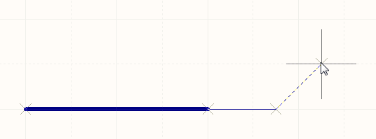 45 degree mode
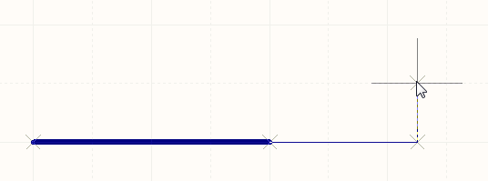 90 degree mode
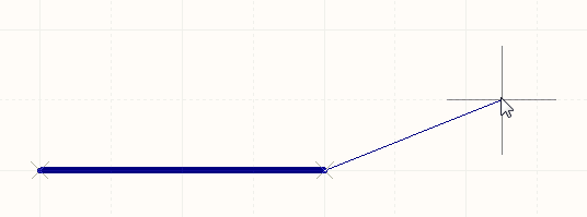 Any angle mode
Press Shift+Spacebar to cycle through the different placement modes.
Non-Graphical Editing...
The following methods of non-graphical editing are available:
...via an Associated Properties Dialog
This method of editing uses the following dialog to modify the properties of a Bus object.
Edit the properties of the Bus in the Bus dialog.
The Bus dialog can be accessed prior to entering placement mode, from the Schematic – Default Primitives page of the Preferences dialog. This allows the default properties for the Bus object to be changed, which will be applied when placing subsequent Buses.
During placement, the dialog can be accessed by pressing the Tab key.
After placement, the dialog can be accessed in one of the following ways:
- Double-clicking on the placed Bus object.
- Placing the cursor over the Bus object, right-clicking and choosing Properties from the context menu.
- Using the Edit » Change command and clicking once over the placed Bus object.
Editing Vertices
The Bus dialog includes a Vertices tab, where you can edit the individual vertices of the currently selected bus object.
Examine or edit individual vertices, click the Menu button for more options.
The main region of the tab lists all of the vertex points currently defined for the bus. Click in a cell to edit a value. You can also add new vertices to the bus, edit the coordinates of existing vertices, or remove selected vertices altogether.
Click the Menu button or right-click within the main list region to access a pop-up menu containing the following commands:
- Edit - right click on a coordinate cell (X or Y) for a vertex and use this command to edit the value in that cell. Alternatively, click directly on the cell.
- Add - use this command to add a new vertex point. The new vertex will be added below the currently focused vertex entry (as distinguished by a dotted outline around a cell in its row) and will initially have the same coordinates as the focused entry.
- Remove - use this command to remove the currently selected vertex entries in the list. This command will be unavailable if there are only two vertices present for the bus.
- Copy - use this command to copy the content of the selected cells in the list to the clipboard (alternatively use Ctrl+C).
- Paste - use this command to paste the content of the clipboard into the list, starting at the selected cell (alternatively use Ctrl+V).
- Select All - use this command to quickly select the entire grid contents of the list.
- Select Column - use this command to quickly select the entire column in which the currently focused cell resides.
- Move Up - use this command to move the selected vertex upward in the list.
- Move Down - use this command to move the selected vertex downward in the list.
- Move Bus By XY - use this command to move the entire bus object. The Move Bus By dialog will appear, from where you can enter the increment value to be applied to each vertex point's X and Y coordinates.
...via the SCH Inspector Panel
The SCH Inspector panel enables the designer to interrogate and edit the properties of one or more design objects in the active document. Used in conjunction with appropriate filtering, the panel can be used to make changes to multiple objects of the same kind, from one convenient location.
...via a List Panel
A List panel allows the designer to display design objects from one or more documents in tabular format, enabling quick inspection and modification of object attributes. Used in conjunction with appropriate filtering, it enables the display of just those objects falling under the scope of the active filter – allowing the designer to target and edit multiple design objects with greater accuracy and efficiency.
Graphical Editing
This method of editing allows you to select a placed bus object directly in the workspace and change its size and/or shape, graphically.
When a bus object is selected, the following editing handles are available:
Selected Bus, ready for graphical editing.
- Click and drag A to reposition the end points of the bus.
- Click and drag B to move a bus vertex. The end points will remain anchored.
- Click and drag on a bus segment to grab that segment and reposition it. The end points and other vertices will remain anchored.
- Right-click on a vertex point and choose the Edit Bus Vertex n command to access the Vertices tab of the Bus dialog, with the entry for the
nthvertex selected ready for editing. - Click and hold on a bus segment, then press Insert on the keyboard to add a vertex at that point.
- Click and hold on a vertex, then press Delete on the keyboard to remove that vertex.
With the bus selected, click on a vertex or segment to individually select that vertex or segment. This bus 'sub-selection' is distinguished by the associated editing handles becoming red in color.
Individual vertex sub-selection.
Individual segment sub-selection.
An individual vertex or a vertex-pair can be sub-selected, ready for editing in the Bus dialog.
The associated vertex (or vertices for a segment) can then be edited directly using the SCH Inspector panel, with any changes appearing immediately on the schematic.
Understanding Bus Connectivity
A bus is used to bundle any number of nets. To do this, the following conditions must be met:
- Each individual net must be identified by a net label.
- The individual nets must be named using the standard naming pattern <Name><NumericalIdentifer1>, <Name><NumericalIdentifer2>, for example
Address0,Address1, ...,Address n. - The bus that the individual nets join must be identified by a net label, in the format <Name>[<StartingNumericalIdentifer>..<EndingNumericalIdentifier>], for example
Address[7..0], or LED[1..8].
Autojunctions
A T-junction in a bus is automatically connected by a junction.
Bus Entries
A bus entry is a short, diagonal section of wire. A bus entry has a single function to perform, to allow an individual net to be ripped out of a bus at the same location another individual net is also ripped out of the bus, as shown in the image below. If a bus entry was not used in this situation, the 2 individual nets would connect together, creating a short-circuit. If it is not necessary to rip 2 individual nets from the same location on a bus, they do not have to be used.
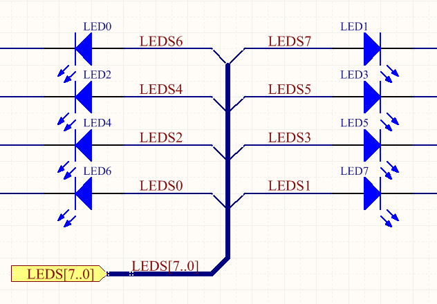
Use bus entries when the nets need to be ripped from both sides of the bus.