Power Port
Parent page: Sch Dialogs
Summary
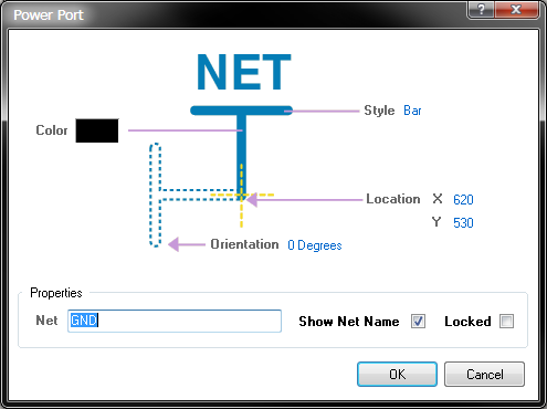
The Power Port dialog allows you to modify the graphical look and feel of the power port object, in addition to associating a specific net to that power port object.
Access
The Power Port dialog can be accessed prior to entering placement mode, from the Schematic – Default Primitives page of the Preferences dialog. This allows the default properties for the power port object to be changed, which will be applied when placing subsequent power ports.
During placement, the dialog can be accessed by pressing the Tab key.
After placement, the dialog can be accessed in one of the following ways:
- Double-clicking on the placed power port object.
- Placing the cursor over the power port object, right-clicking and choosing Properties from the context menu.
- Selecting the Edit » Change command, then clicking once over the power port.
Options/Controls
Appearance
- Color – click the color sample to change the color of the power port.
Style – this field specifies the graphical style of the power object. Available styles are:
Circle,Arrow,Bar,Wave,Power Ground,Signal Ground, andEarth.
- Location X – this field specifies the current X coordinate of the connection point of the power port. Edit the value to change the position of the object in the horizontal plane.
- Location Y – this field specifies the current Y coordinate of the connection point of the power port. Edit the value to change the position of the object in the vertical plane.
- Orientation – this field defines the rotation of the power port symbol relative to the horizontal. Available orientations are:
0 Degrees,90 Degrees,180 Degrees, and270 Degrees.
Properties
- Net – this field specifies the net name for the power object.
- Show Net Name – power ports have net names when they have a net property (connected to a net). By default this option is enabled and the net name associated with this power port is displayed. If you wish to have the net name hidden, disable this option.
- Locked – enable this option to protect the power port from being edited graphically. Lock a power port whose position is critical. If you try to edit a power port that is locked, you will be informed of the locking and asked if you wish to proceed with the action. If this option is disabled, the power port can be freely edited without confirmation.