Graphic
Old Content - visit altium.com/documentation
Parent page: Sch Dialogs
Summary
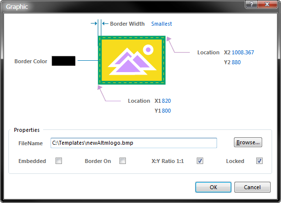
The Graphic dialog allows you to modify properties of the image object, in terms of the image used and the appearance of the frame around that image. The image can be either embedded or linked, and its original aspect ratio can be maintained while scaling to fit within the frame.
Access
The Graphic dialog can be accessed prior to entering placement mode, from the Schematic – Default Primitives page of the Preferences dialog. This allows the default properties for the image object to be changed, which will be applied when placing subsequent image objects.
During placement, the dialog can be accessed by pressing the Tab key.
After placement, the dialog can be accessed in one of the following ways:
- Double-clicking on the placed image object.
- Placing the cursor over the image object, right-clicking and choosing Properties from the context menu.
Options/Controls
- Border Width – this field sets the width of the border drawn around the graphic image. Available widths are:
Smallest,Small,Medium, andLarge. - Border Color – click the color sample to change the color used for the border around the graphic image.
- Location X1 – shows the current X (horizontal) coordinate of the bottom-left corner of the object. Edit the value to reposition this corner in the horizontal plane.
- Location Y1 – shows the current Y (vertical) coordinate of the bottom-left corner of the object. Edit the value to reposition this corner in the vertical plane.
- Location X2 – shows the current X (horizontal) coordinate of the top-right corner of the object. Edit the value to reposition this corner in the horizontal plane.
- Location Y2 – shows the current Y (vertical) coordinate of the top-right corner of the object. Edit the value to reposition this corner in the vertical plane.
- FileName – enter the path and filename of the image to be used directly into this field, or click the Browse button to access a standard Open dialog, with which to search for an image.
- Embedded – enable this option to store a copy of the placed image inside the schematic document. If this option is disabled, only a link to the image file will be stored.
- Border On – enable this option to display a border (or frame) around the image.
- X:Y Ratio 1:1 – enable this option to retain the graphic image's original aspect ratio. The image will be scaled to fit optimally into the frame size specified, while maintaining the original aspect ratio of the image. If this option is disabled, the image is stretched to fit exactly into the drawn frame size, which can lead to distortion of the image.
- Locked – enable this option to protect the image from being edited graphically. Lock an image whose position and/or size is critical. If you try to edit an image that is locked, you will be informed of the locking and asked if you wish to proceed with the action. If this option is disabled, the image can be freely edited without confirmation.