PCBLIB Inspector
Contents
- Summary
- Panel Access
- Defining Panel Display Scope
- Inspecting Object Attributes
- Kind
- Object Specific
- Graphical
- 3D Model Properties
- Editing Object Attributes
- Editing Attributes with Numeric Values
- Modification Using an Expression
- Batch Replacement of String-based Attributes
- Smart Editing of String-based Attributes
- Batch Replace Tab
- Formula Tab
- Notes
Parent page: Panels

Manually select PCB library objects or use the PCBLIB Filter Panel to populate the PCBLIB Inspector panel with objects to be viewed or edited.
Summary
The PCBLIB Inspector panel enables you to interrogate and edit the properties of one or more design objects in the active PCB component footprint (or all component footprints in the active PCB library). Used in conjunction with appropriate filtering, the panel can be used to make changes to multiple objects of the same kind, from one convenient location.
Panel Access
To open the PCBLIB Inspector panel, ensure that a PCB Library is the active document in the editor and click the PCB button ![]() at the bottom-right of Altium Designer, and select the PCBLIB Inspector entry from the pop-up menu
at the bottom-right of Altium Designer, and select the PCBLIB Inspector entry from the pop-up menu
Panels can be configured to be floating in the editor space or docked to sides of the screen. If the PCBLIB Inspector panel is currently in the group of docked Workspace panels on the left, use the PCBLIB Inspector tab located at the bottom of the panels to bring it to the front.
Defining Panel Display Scope
The PCBLIB Inspector panel allows you to define which objects are displayed in the panel (the display scope) via filtering controls. This can be accessed using the underlined control at the top of the panel.
![]()
You may have a large quantity of objects selected in the workspace that are of differing type. Out of all such objects, you may wish to edit the properties of certain object types only, without losing or having to alter your selection.
Clicking on the control will reveal a selection pop-up that allows where you to choose which object types to include in the panel for display and editing - either all objects or specific objects. To choose one or more specific object types, enable the Display only option and then enable the option next to the required object(s) in the list beneath. The list will only contain those object types currently selected in the main workspace.
When specific object types are enabled for display, the control will reflect the choice by listing the enabled types, separated by commas.
![]()
Inspecting Object Attributes
Clicking on a single object in the library design editor window will select that object and display attributes associated to it in the PCBLIB Inspector panel. Information is displayed under the following common collapsible sections:
Kind
This section of the panel contains one entry only, relating to the kind of design object that is being 'inspected'. For example, clicking on a pad will display the entry Pad, clicking on a track will display the entry Track, and so on.
Object Specific
This section of the panel contains attributes specific to the object being inspected and which are not graphical attributes. For example, selecting a 3D body will display attributes that are specific to a 3D body, such as:
- Layer
- Body Projection
- Body 3D Color
- Body 3D Color Opacity
Other selected objects will have different attributes displayed. For example, selecting a pad object will display attributes including Pad Shape/Size, Solder Mask Tenting and Electrical Type.
Graphical
This section of the panel contains graphical attributes of the selected object. Attributes here may include the location of the object, its rotation and whether it is locked.
3D Model Properties
This panel section is exclusive to the 3D Body object, and displays the detailed attributes of the object's 3D Model.
Editing Object Attributes
You can edit attributes of a selected object, by editing the relevant entry in the panel. The change will take effect once you click outside of the field you are editing. This is one of the advantages of using the panel to edit object properties - the panel will remain open, allowing you to change attribute after attribute, as needed, without having to close and reopen a properties dialog each time.
Another advantage of using the panel for editing is that you can edit multiple objects from the one place, without having to edit, through dialogs, one object at a time. Selected objects can be of the same or differing type. Those attributes that are common to all objects in the selection will be displayed in the panel. Common attributes that have differing values between objects will be displayed as <...>. Simply edit the attributes as required - the changes made will be conveyed instantly to each object in the selection.
By using filtering, you can apply a query (an expression for the filter) to target a specific group of objects in one or more component footprints in the active library and then use the PCBLIB Inspector panel to edit the attributes for these multiple objects, directly.
Editing Attributes with Numeric Values
For a numerical-based attribute of a selected object, the simplest modification to that attribute's value is made by typing a new value to replace the existing one. The plus and minus operators can be used to specify the value's sign. A value entered without a specified sign is assumed to be positive. Therefore entering 20 is the same as entering +20.
You can enter specific units of measurement for a value entered. The software will convert the value into the current units defined for the document. If no units are specified, the default units set for the document will be used.
Modification Using an Expression
More advanced modification can be achieved by using an arithmetic expression. Simply select the entry for the attribute you wish to modify and type the expression that will be used to modify its value. You can enter any arithmetic expression, using any built-in arithmetic operators and functions (found in Pascal).
If you wish to use the current value for the attribute as part of the expression, you will need to make reference to this original value, either by using the full name of the attribute, or by using the exclamation character (the supported substitute for the name of the attribute currently being modified). If you wish, you may use any other attribute field name in an expression. When using attribute names, if any names contain spaces, these must be replaced by the underscore character.
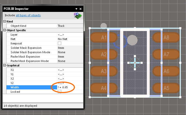
To illustrate an example of using a simple expression, consider the range of tracks used in a component footprint, which might be selected by applying an isTrack query in the PCBLIB Filter panel (with the Select option checked). The footprint uses tracks of different widths (0.1mm, 0.15mm and 0.25mm), as specified by the Width attribute.
If you wanted to add 0.05mm to the width of all tracks, you could enter the expression:
Width + 0.05
...or in shortened form:
! + 0.05
Note that the spaces are optional. When you press ENTER, the track widths are updated to 0.15mm, 0.2mm and 0.3mm.
If instead you want to reduce the size of all tracks by 0.02mm, you could use the subtraction operator, as illustrated by the following expressions:
Width - 0.02
! - 0.02
To illustrate use of a function, the previous expression could be re-written as:
! - sqrt(0.0004)
...the result would be the same - all track widths reduced by 0.02mm.
By using the attribute's name, or the substitution character !, the previous expressions add to or subtract from the current value for the attribute. Without such entries in the expression, you would be setting the attribute's value to the evaluated result of the expression. For example, if the attribute name or substitution character had been left out of the previous expressions, the resulting width value for all the tracks would have been 0.05mml and -0.02mm respectively.
Again, you can enter specific units of measurement for a value entered into an expression. The software will convert the value into the current units defined for the document. If no units are specified, the default units set for the document will be used. By selecting multiple objects in the workspace, as in the example above, you can change numerical attributes simultaneously using an expression. For example, you could also adjust the hole sizes of a series of pads, or shift objects vertically or horizontally by a specific distance.
Batch Replacement of String-based Attributes
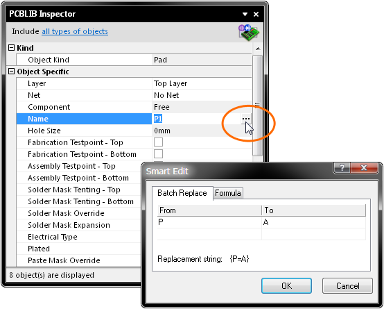
There are times when you may want to modify a string-based attribute that is common to multiple selected objects. For example you may wish to rename the designators of selected pads from A1, A2, A3, etc, to P1, P2, P3, etc. To perform this type of batch replacement, the use of string substitution syntax is supported in the panel.
A string substitution entry is enclosed in braces and has the form: {oldstring=newstring}. An entry of this form causes all occurrences of oldstring found in the attribute's value to be replaced with newstring. In the case of the pad designators, you would enter {A=P) in the value field for the Name attribute.
Should you wish to replace multiple, differing string portions in the same target string, type multiple substitution entries with each enclosed in its own set of curly braces. For example, consider the following free text strings placed as part of the component footprint, where each string indicates the particular port, as well as its ability to communicate with an 8-bit peripheral device:
CommPortA_8
CommPortB_8
CommPortC_8
CommPortD_8
Now consider having modified the device to allow for communications with 32-bit external peripheral devices. Also, it has been requested that the Comm prefix be replaced by IO. The free strings in the PCB component footprint now need to be updated, which is where batch string substitution comes into play.
If the intended format of the new strings is to be IOPortx_32, where x represents the port (A, B, C or D), you could select the four free string objects, access the PCBLIB Inspector panel and enter the following into the value field for the String attribute:
{Comm=IO}{8=32}
The software takes this entry and effectively performs a batch substitution - substituting for the first expression, then the second.
Smart Editing of String-based Attributes
The PCBLIB Inspector panel offers further support for string modification through its Smart Edit feature. Click on a shared attribute of the selected objects, whose value is a string. A button will become available at the far right of the cell. Click on this button to access the Smart Edit dialog.
The dialog offers two methods for performing string modification, accessed from the Batch Replace and Formula tabs respectively.
Batch Replace Tab
This tab provides simple straightforward substitution, along the lines of the string substitution discussed previously (but without having to enter the curly braces). Click the From field and enter the portion of the current string that you wish to replace. Then click the To field and enter the string to be used as the replacement. The familiar string substitution syntax is displayed at the bottom of the tab.
For example, say the pad designators currently have the prefix P, but you need to change them to have prefix A. In this case, select the pads (manually, using the 'Pads' scope, or via the PCBLIB Filter panel), click on the Name attribute in the panel and access the Smart Edit dialog. Then on the Batch Replace tab, enter P in the From field and A in the To field - the replacement string is therefore {P=A}, as shown in the image above. After clicking OK, the designators will be modified accordingly.
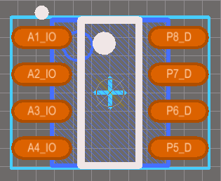
As with basic string substitution, the Batch Replace tab provides for replacement of multiple, differing string portions in the same target string. Simply enter the various substitutions as distinct From-To entries. For example, consider a footprint where the pads are named A1_IO, A2_IO, A3_IO etc, and a selection of those pad names need to be changed from the Ax_IO form to a Px_D form. In this case, you would select the pads to be changed and then enter two distinct substitution entries on the Batch Replace tab.
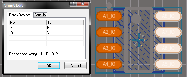
The result is that the name attributes of the selected selected pads are altered in response to the Batch Replace entries.
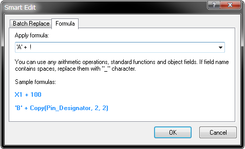
Formula Tab
This tab provides for more advanced modification, allowing you to apply a specific expression to the selected string objects. The expression can include any built-in arithmetic operators and functions that apply to strings (found in Pascal). Once again, if you wish to use the current value for the attribute as part of the expression, you will need to make reference to this original value, either by using the full name of the attribute, or by using the exclamation character (the supported substitute for the name of the attribute currently being modified). When using attribute names, if any names contain spaces, these must be replaced by the underscore character. So, for example, use of the Component Comment field within a formula should be entered as Component_Comment.
A simple formula example might be changing a footprint's pad designators from a 1, 2, 3 sequence to an A1, A2, A3 sequence - or in effect, prefixing the name attribute with 'A'. This would take the added string value ('A') and concatenate it with the existing (original) string value:
'A' + Name
...or, in shortened form:
'A' + !
Note that the spaces are optional. When you press ENTER the designators of the pads will be updated to A1, A2, A3, and so on.
To illustrate the use of string-based functions consider the Copy function, which can be used to take a portion of an original string and place it within an expression to create a new string. Take the Comms Port example (see Batch Replacement of String-based Attributes), where strings of the form CommPortx_8 need to be changed to IOPortx_32. In this case you could select the four free string objects, access the Smart Edit dialog for the String attribute and write the following expression on the Formula tab:
'IO' + Copy(String,5,6) + '32'
...or, in shortened form:
'IO' + Copy(!,5,6) + '32'
Notes
- Pressing the F11 key will toggle the visibility of the panel in the workspace.
- Information will only appear in the panel when either:
1) One or more objects have been selected in the design editor window, or;
2) Object entries are selected in the PCBLIB List panel. - You can use the TAB and SHIFT + TAB keyboard shortcuts to pass down and up the list of attributes in the panel respectively. Alternatively, the arrow keys can also be used.
- When applying a filter using the PCBLIB Filter panel, the attributes for the resulting filtered objects will only be displayed in the PCBLIB Inspector panel if the Select option - located in the Objects passing the filter area of the panel - is enabled prior to application of the filter.
- To de-select objects in the workspace use the Clear button at the bottom-right of Altium Designer