PCB Filter
Contents
- Summary
- Panel Access
- Defining Filter Scope
- Defining Filter Queries
- Query Helper
- Query Builder
- Specifying Precedence
- Historical Queries
- Favorite Queries
- Creating Design Rules
- Defining Filter Highlighting
- Applying and Clearing the Filter
- Right-Click Menus
- Notes
- General:
- When using the Query Builder:
- When building Query Expressions:
Parent page: Panels
Quickly locate and highlight objects using logical queries in the PCB Filter Panel.
Summary
The PCB Filter panel allows you to construct filters through the creation of logical queries. A defined filter can then be applied to the active PCB document, allowing you to select and edit multiple objects with great accuracy and efficiency.
Panel Access
To display the PCB Filter panel, click the PCB button ![]() at the bottom-right of Altium Designer when the PCB Editor is active, and select the PCB Filter entry from the pop-up menu. Alternatively, you can access the panel through the View » Workspace Panels » PCB » PCB sub-menu.
at the bottom-right of Altium Designer when the PCB Editor is active, and select the PCB Filter entry from the pop-up menu. Alternatively, you can access the panel through the View » Workspace Panels » PCB » PCB sub-menu.
Besides these, shortcut key F12 can also be used to launch the panel.

Panels can be configured to be floating in the editor space or docked to sides of the screen. If the PCB Filter panel is currently in the group of docked Workspace panels on the left, use the PCB Filter tab located at the bottom of the panels to bring it to the front.
Defining Filter Scope
The left-hand region of the PCB Filter panel contains controls for defining the scope of the filter. Filtering will be applied to the active PCB document.
The options available are:
- All objects - apply the filter to all design objects.
- Selected objects - apply the filter only to those design objects that are currently selected.
- Non selected objects - apply the filter only to those design objects that are not currently selected.
Defining Filter Queries
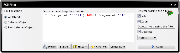
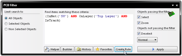
The central region of the PCB Filter panel allows you to construct filters through the entry of logical queries.
You can type a query directly into the field, and as you type, a prompt list of possible keywords will appear as an aid.
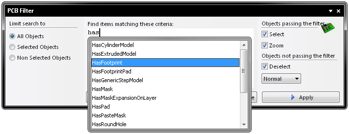
Two facilities are available to provide aid in the creation of queries - the Query Helper and the Query Builder. These facilities can be very useful if you are unsure of the syntax of a query or the possible keywords that you may want to use.
Query Helper
To use the Query Helper, click the Helper button to open the Query Helper dialog. The underlying Query Engine analyzes the document and lists all available objects, along with generic keywords for use in queries.
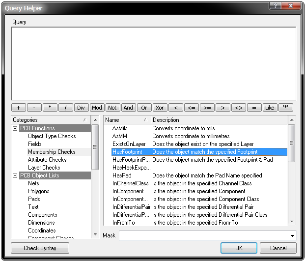
Use the top section of the dialog to compose a query expression, using the available PCB Functions, PCB Object Lists and System Functions. The mid-section of the dialog provides a range of operators for use when constructing an expression. Use the Check Syntax button to verify that an expression is syntactically correct.
When the expression for the query has been defined as required, clicking OK will load the central region of the PCB Filter panel with the query, ready to apply the filter.
Query Builder
To use the Query Builder, click the PCB Filter panel's Builder button to open the Building Query from Board dialog.
This dialog enables you to create a query for targeting specific objects in the design document, by simple construction of a string of ANDed and/or ORed conditions.
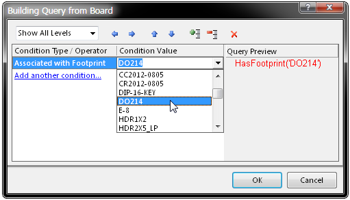
The left-hand section of the dialog is where you specify the condition(s) that you require to target the set of objects needed. Initially the entry in the Condition Type/Operator column will be Add first condition. Clicking once on this entry will reveal a drop-down list of condition types.
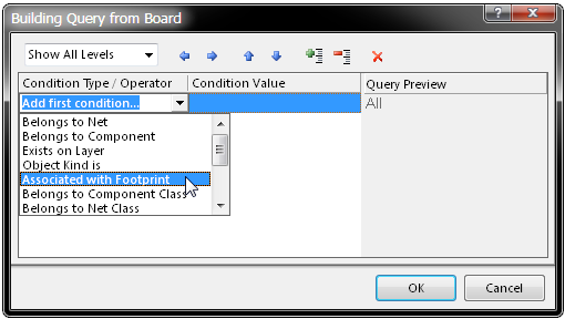
The condition types listed will only reflect those relevant to a board design.
Select the condition and click in the Condition Value column to access a drop-down list of possible values for that condition type. As you define a condition in the left-hand section of the dialog, a preview of the currently built query is shown in the right-hand section.
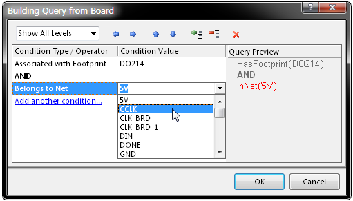
Continue to add further conditions to narrow down your target set of design objects as required. Conditions can be ANDed or ORed together. The default logical operator is AND, which is automatically inserted when you add another condition.
To change the logical operator between conditions, click on the AND or OR entry in the Condition Type/Operator column and select the required operator. The preview of the query will update accordingly.
Specifying Precedence
The ![]() and
and ![]() buttons at the top of the PCB Filter dialog allow you to essentially add and remove brackets around the presently selected condition (increasing and decreasing indent). This allows you to create precedence for certain logically ANDed or logically ORed conditions.
buttons at the top of the PCB Filter dialog allow you to essentially add and remove brackets around the presently selected condition (increasing and decreasing indent). This allows you to create precedence for certain logically ANDed or logically ORed conditions.
For example, consider the following built query:
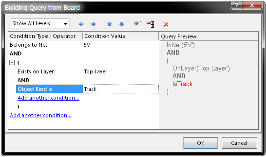
(InNet('5V') AND (OnLayer('TopLayer') AND IsTrack))
The first condition has been set to the condition type Belongs to Net, with value 5V. Another condition has then been added, using the condition type Exists on Layer, with the value TopLayer.
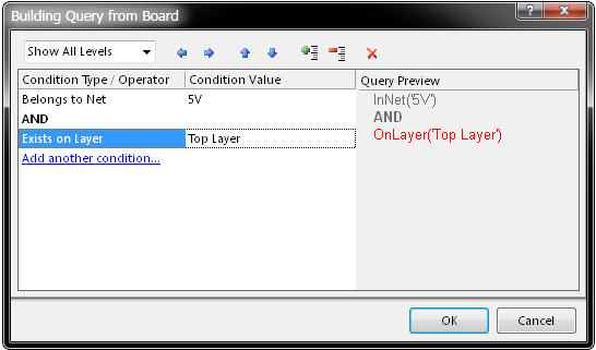
At this stage, with the second condition selected in the dialog, the right arrow button has been clicked. Brackets have been automatically added around the second condition, and now the possibility to add a condition within that pair of brackets is available.

The third condition with condition type Object Kind is and value Track is then added within the brackets.
Use the Show Level drop-down at the top-left of the dialog to control the visual display of levels in your structured string of conditions. This essentially expands/collapses the display of brackets. Adding brackets effectively creates a new level. You can display levels 1-5, but for any further levels added use the Show All Levels option.
Alternatively, click on the expand ![]() or contract
or contract ![]() symbols (associated with a bracketed condition) to show the next level(s) or hide the current level (and all levels below) respectively. The
symbols (associated with a bracketed condition) to show the next level(s) or hide the current level (and all levels below) respectively. The ![]() and
and ![]() buttons at the top of the dialog can also be used to expand or collapse the currently selected condition.
buttons at the top of the dialog can also be used to expand or collapse the currently selected condition.
Use the ![]() and
and ![]() buttons at the top of the dialog to move a selected condition in the query string being built. For a condition that has sub-levels (i.e. a bracketed condition), any condition in the level structure can be moved. When levels are expanded, a condition can be moved down or up through the levels. When levels are collapsed, a condition will be moved over the level structure.
buttons at the top of the dialog to move a selected condition in the query string being built. For a condition that has sub-levels (i.e. a bracketed condition), any condition in the level structure can be moved. When levels are expanded, a condition can be moved down or up through the levels. When levels are collapsed, a condition will be moved over the level structure.
To delete a condition, select it and either click the ![]() button at the top of the dialog, or use the DELETE key.
button at the top of the dialog, or use the DELETE key.
When the expression for the query has been defined as required, clicking OK will load the central region of the PCB Filter panel with the query, ready to apply the filter.
Additional buttons in this region of the panel provide access to previously used and favorite (stored) queries, as well as the ability to create design rules. The following drop-down sections look at these features in more detail.
Historical Queries
As you enter and apply a new query, it will be added to a query history list. Click the History button in order to access this list - the Expression Manager dialog will open, with the History tab active.
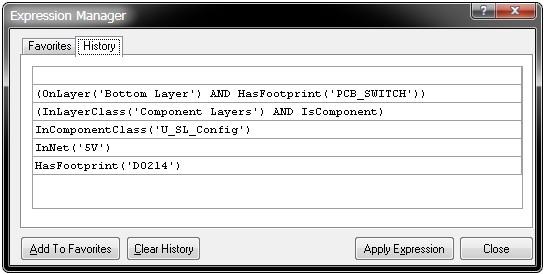
To use an historical query from the list, either select its entry and click on the Apply Expression button, or double-click on the entry directly. The dialog will close and the expression for the query will be loaded into the central region of the PCB Filter panel.
An historical query can be added to the list of favorite queries, by selecting its entry and clicking the Add To Favorites button. Use the Clear History button if you wish to 'flush' the history list. Up to nine most recently used query expressions from the list will be available for use from the panel's right-click menu.
Favorite Queries
Any defined query may be added to a list of favorite queries in two ways:
- By using the Add to Favorites command from the panel's right-click menu - to add the query expression currently defined in the central region of the panel.
- By selecting an historical query entry in the History tab of the Expression Manager dialog and clicking the Add To Favorites button.
Click the Favorites button in the PCB Filter panel in order to access this list - the Expression Manager dialog will appear, with the Favorites tab active.
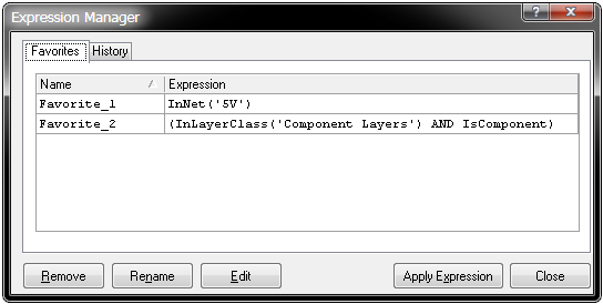
To use a favorite query from the list, either select its entry and click on the Apply Expression button, or double-click on the entry directly. The dialog will close and the expression for the query will be loaded into the central region of the PCB Filter panel.
When a query expression is added to the favorites list, it is assigned a unique name. By default, a generic name is assigned - Favorite_n - where n is the next available unused number. The name for an entry can be changed at any stage by using one of the following methods:
- Selecting the query entry and clicking the Rename button.
- Selecting the query entry and choosing the Change command from the available right-click menu.
- Selecting the query entry and then clicking again within the Name field.
In each case, type the new name as required and click outside the Name field to effect the change.
To remove a query from the favorites list, select its entry in the list and either click on the Remove button or choose the Remove command from the available right-click menu. A dialog will appear requesting confirmation of the removal. Up to ten most recently added query expressions to the list will be available for use from the top of the panel's right-click menu. Note that the content of the Favorites list is common to (and accessible from) both the PCB Filter and PCBLIB Filter panels.
Creating Design Rules
The PCB Filter panel also provides the facility for creating a design rule, where its scope will use the currently defined query expression in the central region of the panel.
To add a new design rule, click on the PCB Filter panel's Create Rule button. The Choose Design Rule Type dialog will appear.
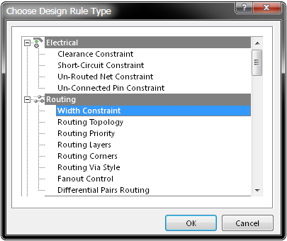
This dialog lists each of the rule categories and rule types that are available in the PCB document. Simply choose the type of rule you wish to create and click OK (or double-click directly on the entry). The PCB Rules and Constraints Editor dialog will appear.
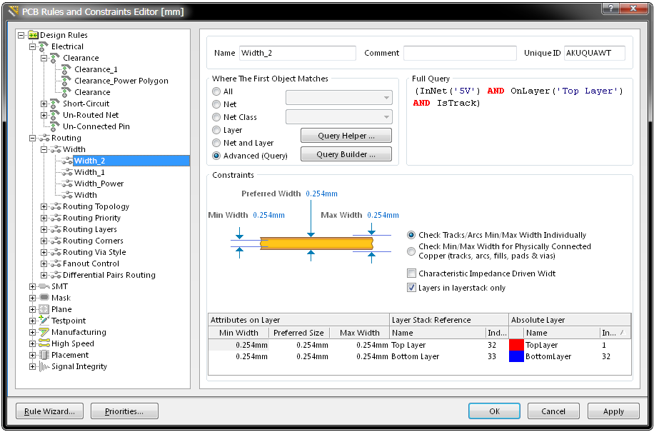
The newly created rule name can be seen selected in the left side navigation tree. The rule query expression is in the dialog's top-right pane.
A rule of the chosen type is created and the main editing window for the rule is displayed, ready for you to define specific constraints for the rule. The query expression from the PCB Filter panel is entered into the Full Query region of the dialog. Refine the rule configuration settings as required, and apply the new rule.
Defining Filter Highlighting
Before application of the query in the PCB Filter panel, it is best to define how you wish the result of the filtering to appear visually in the design workspace. The right-hand region of the panel provides various options which collectively form the highlight controls for permanent filtering.
The 'Objects passing the filter' options allow you to control how all objects that fall under the scope, and match the specific query expression of the filter, will be visually displayed in the workspace.
- Select - when enabled (default), the filtered objects will be selected in the workspace.
- Zoom - when enabled (default), the filtered objects will be zoomed and centered (where possible) in the design editor window.
Conversely, the 'Objects not passing the filter' options allow you to control how all objects that do not fall under the scope, and/or match the specific query expression of the filter, will be visually displayed in the workspace.
- Deselect - when enabled (default), all objects not falling under the scope of the filter will be deselected in the workspace.
- Mask / Dim / Normal - this dropdown list provides you with options for visibly contrasting filtered and unfiltered objects within the design editor window. The effectiveness of masking and dimming is determined by the Highlighting Options set in the PCB Editor - Display page of the Preferences dialog.
Controls for adjusting masking and dimming are accessed by clicking the Mask Level button ![]() at the bottom-right of Altium Designer.
at the bottom-right of Altium Designer.
- When Mask is selected in the PCB Filter panel options, filtered objects will appear visible in the design editor window, with all other objects being made monochrome. To set the contrast of the background (un-highlighted) objects, click Mask Level button at the bottom-right of Altium Designer when the PCB Editor is active:
When this option is applied, unfiltered objects will be unavailable for selection or editing. - When Dim is selected in the panel options, filtered objects will appear visible in the design editor window, with all other objects retaining their colors, but being shaded. Set the balance between filtered and unfiltered objects using the Masked Objects Factor and Highlight Objects Factor sliders after clicking Mask Level button :
- When Normal is selected, filtered objects are highlighted, however, the appearance of unfiltered objects remains unchanged.
Any combination of these options can be enabled. For example, you might want to have all filtered objects that fall under the scope of your query to be zoomed, centered and selected in the design editor window, whilst applying masking to take away the clutter of other design objects.
Applying and Clearing the Filter
Once you have defined your query and set up the options in the panel as required, the filter can be applied - either by clicking the panel's Apply button or pressing ENTER.
An applied example of the filter used above; (InNet('5V') AND (OnLayer('TopLayer') AND IsTrack)). The visual result is zoomed, dimmed and the objects are not selected.
To clear the currently-applied filter from within the panel, clear (select and delete) the query expression in the central region of the panel and either click the Apply button or press ENTER. All objects in the design workspace will be restored to full visibility and be available for selection/editing.
Alternatively, to clear filtering in the workspace, but leave the query expression loaded into the central region of the panel, use the Clear button at the bottom right of the design editor window.
Right-Click Menus
Right-clicking within the PCB Filter panel provides access to additional options and commands via a pop-up menu.

The menu provides the following commands:
- Add to Favorites - use this command to add the query expression currently displayed in the central region of the panel to the list of favorite queries. The query will appear as a new entry on the Favorites tab of the Expression Manager dialog. As a query is added to the list of favorite queries, it will be displayed at the top of the right-click menu. The ten most recently added queries to the favorites list will be displayed on the menu (most recent at the top), enabling you to quickly access and reuse your favorite query expressions.
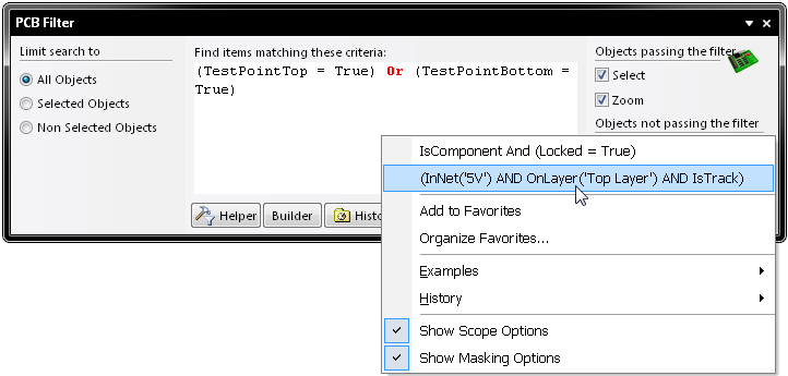
- Organize Favorites - use this command to access the Favorites tab of the Expression Manager dialog, from where you can organize (rename, delete) entries in the list of favorite queries.
- Examples - click to access a sub-menu of predefined example filters. Choosing an example filter will load the associated, underlying query expression into the central region of the panel.
- History - click on this entry to access a sub-menu containing the nine most recently used query expressions, taken from the query history list for the panel. Click on the More entry to access the History tab of the Expression Manager dialog, from where you can browse through and apply a query from the full list of historical queries and also clear the history list as required.
- Show Scope Options - use this command to toggle the display of the filter scope (left-hand) region of the panel.
- Show Masking Options - use this command to toggle the display of the filter highlighting (right-hand) region of the panel.
Notes
General:
- Pressing the F12 key will toggle the visibility of the panel in the workspace.
- The Query Builder (Building Query from Board dialog) provides a simple method of constructing a query, using sensitive condition types and values that only allow you to build using relevant 'building blocks'. For advanced query construction, with full keyword specification and operator syntax, use the Query Helper dialog.
- When using the Query Helper dialog to construct a query, clicking inside a typed keyword or on a keyword in one of the available lists and pressing F1 will launch help for that particular keyword. Similar access to keyword-level help is available by clicking within a keyword in the central region of the PCB Filter panel and pressing F1.
- As the display options for objects passing and not passing the applied filter are separated, you can effectively apply new filter queries to build upon the results of previous filtering.
- Filtering applied when using Queries from the PCB Filter panel is permanent for the session. A permanent filter must be cleared by clicking on a corresponding Clear button (e.g. at the bottom-right of the design editor window) or by applying an empty query from the PCB Filter panel.
- Depending on the shape and size of the PCB Filter panel itself, the content will be dynamically arranged horizontally or vertically.
When using the Query Builder:
- You can adjust any condition in your query string, at any time, by clicking on the entry for that condition in the Condition Type/Operator column and choosing the required new condition from the available entries in the drop-down list. Again, the preview of the query will update accordingly.
- The currently selected condition or logical operator in the left side of the dialog is visually confirmed in the preview section of the dialog by the entry appearing in red text.
- Use CTRL + Up Arrow and CTRL + Down Arrow keyboard shortcuts to move the selected condition entry up or down in the structure respectively.
- Use CTRL + Right Arrow and CTRL + Left Arrow keyboard shortcuts to increase or decrease indent at the selected position in the structure (add/remove brackets) respectively.
When building Query Expressions:
- It is highly advisable to use brackets whenever there is any possibility whatsoever that the query might not be correctly interpreted.
- Brackets have the highest precedence within an order of precedence that has been defined for the various operators provided and which determines how queries are interpreted by the software (whenever the user has not provided brackets). The sequence of this order is as follows:
Brackets
Not
^, *, /, Div, Mod, And
+, -, Or, Xor
=, <>, <, >, <=, >=
&&, ||
This order of precedence is similar to that used in Pascal type languages. However, generous usage of brackets removes doubt and makes the resulting queries easier to read by others. - Ambiguities are resolved by working from left to right.
- Parentheses are evaluated from inside to outside and equal levels are done left to right.