Violation
Parent page: Objects
Design rule violations are clearly marked by Violation Objects.
Summary
A violation object marks where one or more design objects are violating a design rule. Violation objects are also known as DRC (Design Rule Check) Error Markers.
Availability and Placement
Violation objects are automatically placed by the Design Rule Checking feature, they are not objects that are placed or edited by the designer. When either the online or the batch DRC is run, each design object that violates a design rule is marked by a violation object. The rules that are currently being checked are configured in the Design Rule Checker dialog (Tools » Design Rule Check), as shown below.
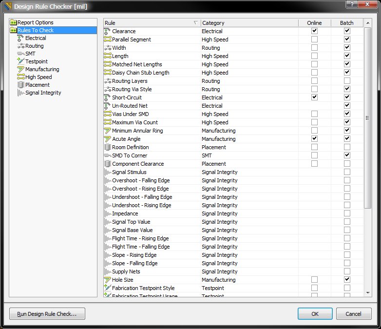
Both online and Batch rule checking is configured in the Design Rule Checker dialog. Each design object that violates a rule is marked by a violation object.
Presentation of Violation Objects
There are 2 types of violation objects, DRC Error Markers and DRC Detail Markers.
- DRC Error Markers - these are markers applied to the entire object that is in violation, regardless of the location of that violation. These objects make it easy to quickly see where there is a violating object, regardless of the zoom level.
- DRC Detail Markers - detail markers show the location and the reason a design rule is in violation. These markers give instant feedback on the condition that is being violated, and are placed at a violation location.
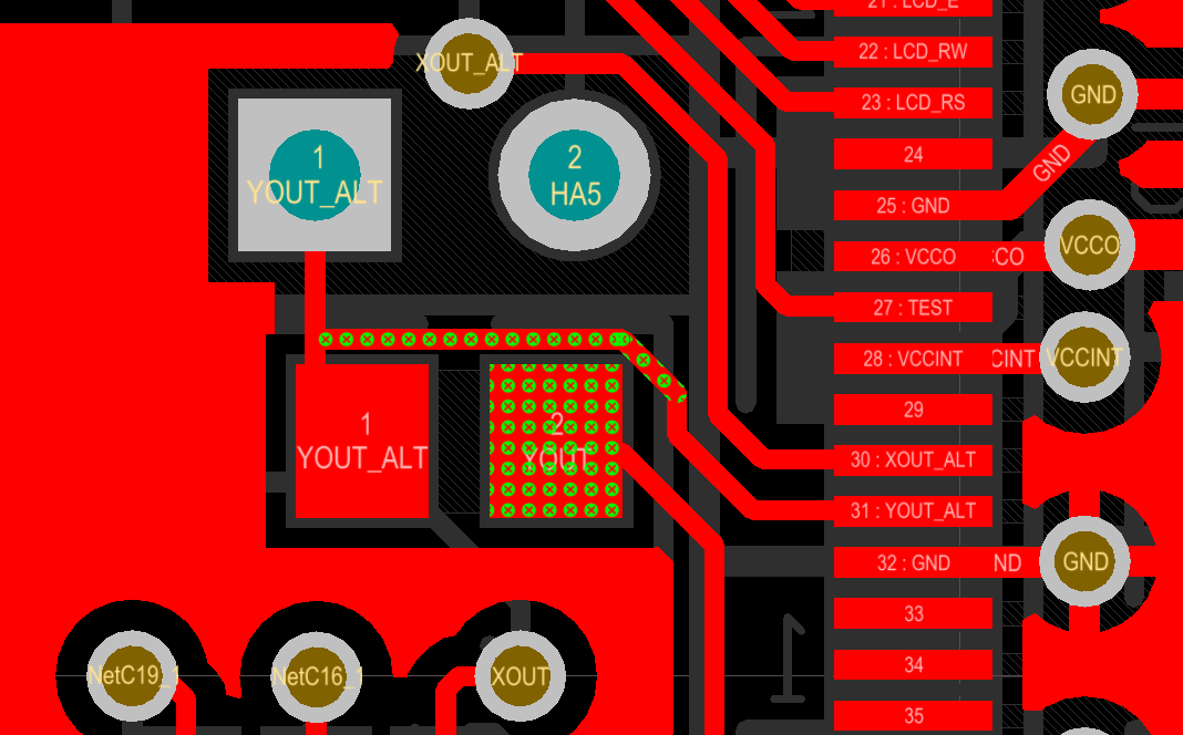
The images below show how the 2 types of markers work together - the images on left are zoomed out, the images on the right are zoomed in on the same violations. The upper-left image shows clearance violations marked by a DRC Error Marker (in green), the upper-right image shows both the green Error Marker and also the white Detail Marker, indicating that the clearance is less than the 0.2 mm specified in the applicable Electrical Clearance design rule. The lower images shows vias that are violating, in the lower-right image the Detail Maker shows that the via is less than the 1mm specified in the applicable Via Style design rule.
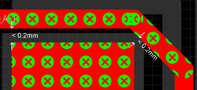
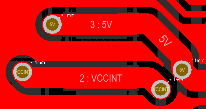
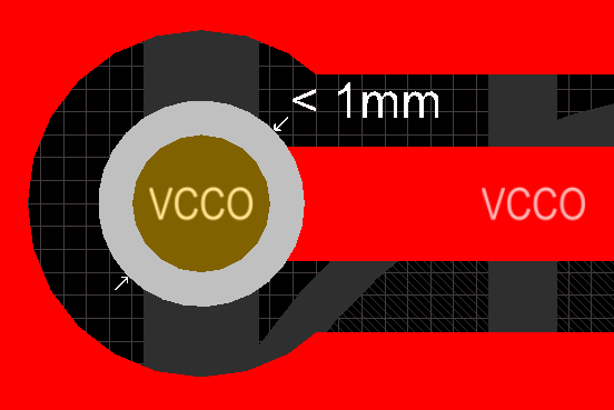
Marked violations shown at different zoom levels. Error Markers can be seen regardless of the zoom level, identify the object(s), zoom in to see Detail Markers and the actual violation.
The presentation of the violation objects can be configured in the following ways.
DRC Marker Colors
The color of both types of markers are configured in the Board Layers and Colors tab of the View Configuration dialog. The System Colors section of this tab is shown below:

Configure the color of the Error and Detail Markers in the View Configurations dialog.
Error Marker Style and Zoom Behavior
In the images above the DRC Error Markers are shown as solid yellow when zoomed out, and as yellow dots with a cross when zoomed in. The presentation behavior of these markers can be configured in the PCB Editor - DRC Violations Display page of the Preferences dialog. There are 2 aspects that can be configured (refer to the image below):
- Violation Overlay Style - error markers can be shown as a Solid Override Color, as a warning triangle (Style A), as a dot with a cross (Style B), or not shown at all (None).
- Overlay Zoom Out Behavior - error markers can remain the same regardless of the zoom level (Base Pattern Scales), revert to the layer color (Layer Color Dominates), or become a solid color (Override Color Dominates).
The point at which the display changes while zooming is then controlled by the Show Violation Detail slider.
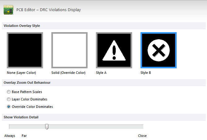
Configure the Overlay Style (Style B in this example) and how Error Markers are displayed at different zoom levels.
When Violations are Marked
The enabled design rules determine which rules are checked and when they are checked (online and/or batch). How detected violations are then marked is determined by the DRC Violation Display Style settings in the PCB Editor - DRC Violations Display page of the Preferences dialog.
As the designer you can configure the display to show just the Violation Details (Detail Markers), or to show a Violation Overlay (Error Markers), or both. Enable the check boxes as required, or right-click in the dialog to toggle multiple options on or off.
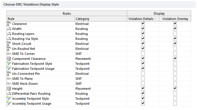
Enable which violations will display as Details, using an Overlay, or both.
Understanding the Violations
There are a number of ways violation information is displayed within the software. The violation markers (both Overlay and Detail) provide strong clues to the location and nature of the violation. For example, in the image below the via on the left has a detail marker that shows the diameter of the via is less than 32mils, so it must be smaller than the size allowed in the Via Style design rule. There is also a line drawn from the via to a pad that is nearby, and this line is broken by a double-slash. This indicates that the net is un-routed (broken) between the via and pad. Use the detail markers to help interpret the error condition.
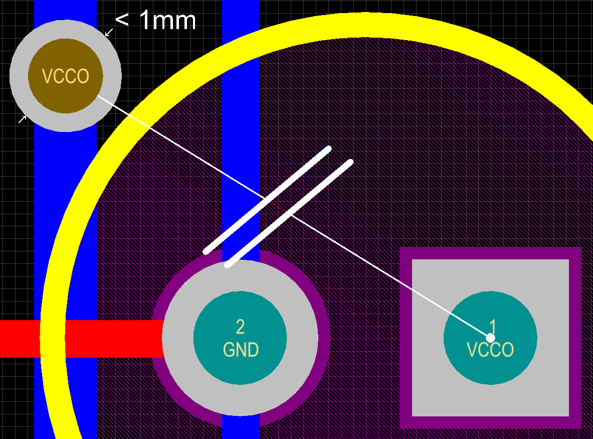
Detail Markers showing a via that is under-sized, and an un-routed net.
As well as the markers, all detected violations are detailed in the PCB Rules and Violations panel (View » Workspace Panels » PCB » PCB Rules And Violations). The image below shows a section of the panel with the Un-Routed Net Constraint selected, below that it shows that there is 1 Rule selected, below that it shows there is 1 Violation.
Use the PCB Rules and Violations panel to quickly locate design rule violations.
Click once on a violation to zoom to that violation in the workspace, double-click on it to open the Violation Details dialog, which details both the Violated Rule, and the Violating Primitives.
The Violation Details dialog shows both the rule and the primitives involved with the error condition.
Clearing Violation Objects
Violation objects can be removed by running the Reset Error Markers command, click Tools » Reset Error Markers. Note that this simply removes the error markers, the underlying design rule violations must still be analyzed and resolved.