User-defined FromTo
Parent page: Objects
User-defined From To.
Summary
User-defined From Tos allow you to create specific net topologies within a design, giving you total control over the arrangement, or pattern, of pin-to-pin connections in a net. They are different to system-generated From Tos, added and arranged by the PCB Editor to give the shortest overall connection length in each case
- a net topology referred to as Shortest.
Displayed in the workspace as pin-to-pin connection lines, From Tos are collectively referred to as the 'ratsnest'.
Availability & Placement
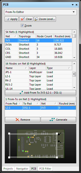
User-defined From Tos can be added for part or all of a net using the From-To Editor, available from the PCB panel.
Non-Graphical Editing
A user-defined From To object cannot be edited with respect to properties in the usual manner - it cannot be selected in the workspace, has no corresponding properties dialog and cannot be edited graphically.
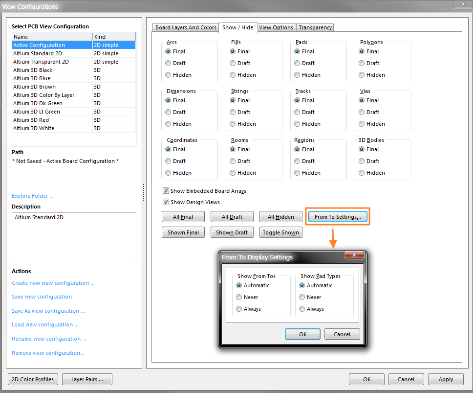
The View Configurations dialog.
The display of user-defined From Tos is controlled from the From To Display Settings dialog, accessed via the From To Settings button on the Show/Hide page of the View Configurations dialog. You can save view configurations for use in other projects.
By default, display of user-defined From Tos is set to Automatic . In this mode, the From Tos can only be viewed when the PCB panel is configured in From-To Editor mode. To be able to see user-defined From Tos when browsing nets or components in the design (PCB panel in Nets or Components modes), set the display mode to Always .
Notes
- A system-generated From To does not appear in the workspace as a separate entity. Only the associated pin-to-pin connection line for the From To is displayed, which is used for interactive routing/Autorouting guidance.
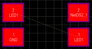
- A user-defined From To appears in the workspace as a dotted line, separate and distinct from the pin-to-pin connection line that is also displayed when the From To is added. The user-defined From To line controls where the associated pin-to-pin connection line starts and finishes. This is best demonstrated by example. Consider a user-defined From To added between the logically connected pins of two components. A connection line is also added and displayed (PCB panel configured in Nets mode; From To display set to Always):

- The pin-to-pin connection line - used for routing purposes - conceals the presence of the distinctly separate user-defined From To line. However, as you start to route the connection, you can see the distinct and separate nature of the two lines:
- If the routing is now suspended, the Connectivity Analyzer adds a connection line so as to maintain the required topology which is shown as a dotted line (called a Broken Net Marker), indicating that the net should be routed between these two points to maintain the topology determined by the user through the addition of the user-defined From To:
- If you specify user-defined From Tos for only part of a net, the PCB Editor will set the remaining pin-to-pin connections (system-generated From Tos) to the Shortest topology.
- The type of From To determines how the Connectivity Analyzer treats the connection line in the workspace when, for example, a net object is moved or part of a net is manually routed:
- System-generated From To
- the connection line can be moved as required as part of the Connectivity Analyzer's re-optimization to keep the default topology of the net (i.e. Shortest) - User-defined From To
- if the From To is not the result of selecting a predefined topology, the connection line is not considered as part of the Connectivity Analyzer's re-optimization process. If the From To is part of a predefined net topology (other than Shortest), the Connectivity Analyzer can include it in re-optimization, so long as the chosen topology is kept.