Region
Parent page: Objects

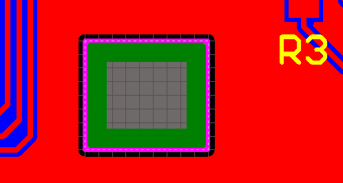
Region objects used to define a logo, created by copying from an image editor (MS Paint) and pasting into the PCB editor.
Summary
A Region, also known as a Solid Region, is a polygonal-shaped primitive object that can be placed on any layer. It can be configured to be positive, for example placed as a copper region; or negative, for example placed as a polygon pour cutout. By placing it as a negative on the multi-layer, it can be placed as a board cutout.
A region can have any number of sides and vertices (corners). It can be placed on a signal layer to define an area of solid copper, to be used to provide shielding or to carry large currents. Positive regions can be combined with tracks or arc segments and be connected to a net. In the PCB Library editor regions can be used to create custom pad shapes on copper layers, or special mask shapes on the solder and paste masks. On non-electrical layers regions can be used to define custom shapes for tasks such as logos, which is how it is used when a bitmap is copy/pasted into the PCB editor (as shown in the image above).
A region can also be used to define no-go areas for component placement and routing, which are also known as keep-outs. These can apply to all layers by placing the region on the Keep-out layer, or they can be layer-specific by placing the region on a signal layer and enabling the Keep-out option for that region.
When placed as a negative, a region can create a cutout (a void) in a polygon pour. In this mode the region will not be filled with copper when the polygon is poured. When used as a negative region for a board cutout (by placing it on the multi-layer), it defines an area that become a hole through the finished board. Board cutout regions are transferred to Gerber and ODB++ files for manufacturing purposes.
Availability
Regions are available for placement in both the PCB editor and the PCB Library editor.
PCB Editor
Use the following method to place a region in the PCB editor:
- Click the
 button, found in main menu at Place » Solid Region.
PCB Library Editor
Use the following method to place a region in the PCB Library editor:
- Click the button, found in main menu at Place » Solid Region.
Placement
After launching the command, the cursor will change to a crosshair and you will enter region placement mode. Placement is made by performing the following sequence of actions:
- Position the cursor and click to anchor the starting vertex for the region.
- Move the cursor ready to place the second vertex. The default behavior is to place 2 edges with each click (as shown in the first 5 images in the set below), with a user-defined corner shape between them. Refer to the Placement Modes topic below for more details on changing corner modes.
- Continue to move the mouse and click to place further vertices.
- After placing the final vertex, right-click or press Esc to close and complete placement of the region. There is no need to manually close the region as the software will automatically complete the shape by connecting the start point to the final point placed.
- Continue placing further regions, or right-click or press Esc to exit placement mode.
Additional actions that can be performed during placement include:
- Press the + and - keys on the numeric keypad to cycle forward and backward through all layers currently visible in the design.
- Press the * key to cycle through the visible signal layers.
- Press the Tab key to access an associated properties dialog, from where properties for the region can be changed on-the-fly.
Placement Modes
While placing a region there are 5 available corner modes, 4 of which also have corner direction sub-modes. During placement:
- Press Shift+Spacebar to cycle through the 5 available corner modes: 45 degree, 45 degree with arc, 90 degree, 90 degree with arc, and Any Angle.
- Press Spacebar to toggle between the two corner direction sub-modes.
- When in either of the arc corner modes, hold the or keys to shrink or grow the arc. Hold the Shift key as you press to accelerate arc resizing.
- Press the 1 shortcut key to toggle between placing 2 edges per click, or one edge per click. In this second mode the dashed edge is referred to as the look-ahead segment (as shown in the last image in the set below).
- Press the Backspace key to remove the last vertex.
Press Shift+Spacebar to cycle through the 5 available corner modes, press the 1 shortcut to toggle placement between 2 edges or 1 edge.
Placing a Region as a Keepout
A region can be placed as a layer-specific keepout object or an all-layer keepout to act, for example, as a placement or routing barrier. Objects defined as keepouts are ignored during output generation, such as photo plotting and printing. A layer-specific keepout region is simply a region object with its Keepout property enabled, an all-layer keepout is a region that has been placed on the Keepout layer.
- To place a layer-specific keepout either place a standard region on the required signal layer and then enable the Keepout property to make it a layer-specific keepout, or use the predefined Solid Region keepout placement command, available in the sub-menu in main menu at Place » Keepout » Solid Region.
- To place an all-layer keepout, make the Keepout layer the active layer, then place a region from the menu (Place » Keepout » Solid region).
Placing a Region as a Polygon Cutout
A Region can also act as a polygon cutout. To place a polygon cutout:
- Place a standard region over the polygon and then enable the Polygon Cutout option in the dialog to achieve this.
- Repour the polygon to pour around the new cutout using one of the Repour commands available in main menu at Tools » Polygon Pours.
Placing a Region as a Board Cutout
A Region can also act as a board cutout. To place a board cutout:
- Place a standard region over the board shape and then edit the region and enable the Board Cutout option in the dialog to achieve this, or,
- Place a board cutout directly via the menu at Design » Board Shape » Define Board Cutout.
- Repour any polygons that overlay the board cutout using one of the Repour commands available on the menu at Tools » Polygon Pours.
Important Design Considerations When Using Board Cutouts
Keeping the Polygon Back from the Edge of a Board Cutout
Note that polygons that overlay a solid region board cutout will pour up to the edge of the cutout. If the polygons must be pulled back from the edge of the board cutout a keepout must be defined around the edge of the cutout. While the keepout can be created manually by placing lines and/or arcs on the keepout layer, a better way is to get the software to place suitable objects.
To define a keepout boundary around the edge of the board cutout:
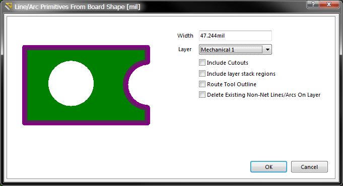
- Run the Create Primitives from Board Shape command, available in main menu at Design » Board Shape. The Line/Arc Primitive From Board Shape dialog will appear.
- Define a suitable Width for the keepout objects. Remember that the objects created will be placed with their center line along the edge of the cutout, so half of the keepout object width will be on the board. The Design Rules will then pull the polygon further back from the keepout to satisfy the applicable Clearance design rule, so the final distance from the edge of the cutout to the edge of the polygon will be
KeepoutWidth/2 + DesignRuleClearance. - Set the Layer option to the Keepout layer.
- Enable the Include Cutouts option and click OK to create the Keepout primitives.
- Repour any polygons that overlay the board cutout using one of the Repour commands available in main menu at Tools » Polygon Pours.
Use the software to create a keepout boundary around the edge of a board cutout.
Defining a Rout Tool Path Around the Edge of the Board and Cutouts
A common approach used to cut the finished board from the fabrication panel is to mill or rout the board out of the panel. Board cutouts can also be routed out. A Rout Tool path is defined by placing Line and/or Arc objects on a mechanical layer. This can be done manually, or automatically by the software.
To define a Rout Tool path for the board and any board cutouts:
- Run the Create Primitives from Board Shape command, available in main menu at Design » Board Shape. The Line/Arc Primitive From Board Shape dialog will appear.
- Define a suitable Width for the objects that will define the Rout Tool path. Consult with your fabricator if you are unsure of this.
- Select an available mechanical layer, this layer should be reserved for just the Rout Tool path definition.
- Enable the Include Cutouts option if the board has cutouts in it. The difference with this option is that the line/arc objects are placed so their edge touches the edge of the board shape and the edge of the cutout.
- Enable the Rout Tool Outline option, and click OK to create the Rout Tool objects on the chosen mechanical layer.
- The mechanical layer used must be set as the Rout Tool layer, to do this open the Board Options dialog (right-click in the workspace and select Options » Board Options) and select the required Layer in the Rout Tool Path option.
The images below show the Rout Tool path defined on a mechanical layer.
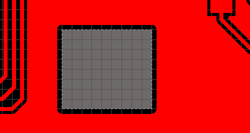
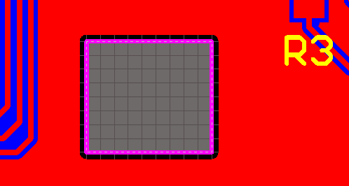
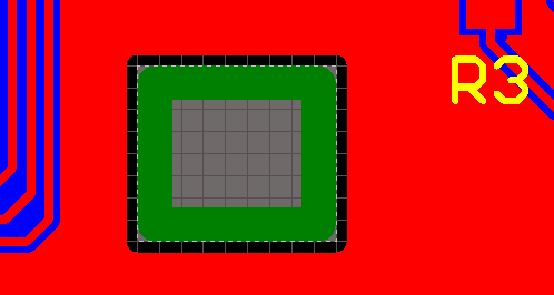
A Board Cutout (1st image), with a keepout defined to keep the polygon back (2nd image), and a Rout Tool path defined (3rd image), then all objects visible (4th image).
Non-Graphical Editing...
The following methods of non-graphical editing are available:
...via an Associated Properties Dialog
This method of editing uses the following dialog to modify the properties of a region object.
Edit the properties of the Region in the dialog.
The Region dialog can be accessed prior to entering placement mode, from the PCB Editor – Defaults page of the Preferences dialog. This allows the default properties for the region object to be changed, which will be applied when placing subsequent regions.
During placement, the dialog can be accessed by pressing the Tab key.
After placement, the dialog can be accessed in one of the following ways:
- Double-clicking on the placed region object.
- Placing the cursor over the region object, right-clicking and choosing Properties from the context menu.
- Run command Edit » Change, then click an existing object.
Editing Vertices
The Region dialog includes an Outline Vertices tab, where you can edit the individual vertices of the currently selected region object.
Examine or edit individual vertices, click the Menu button for more options.
Click the Menu button or right-click within the main list region to access a pop-up menu containing the following commands:
- Edit - right click on a coordinate cell (X or Y) for a vertex and use this command to edit the value in that cell. Alternatively, click directly on the cell.
- Add - use this command to add a new vertex point. The new vertex will be added below the currently focused vertex entry (as distinguished by a dotted outline around a cell in its row) and will initially have the same coordinates as the focused entry.
- Remove - use this command to remove the currently selected vertex entries in the list. This command will be unavailable if there are only two vertices present for the wire.
- Copy - use this command to copy the content of the selected cells in the list to the clipboard (alternatively use Ctrl+C).
- Paste - use this command to paste the content of the clipboard into the list, starting at the selected cell (alternatively use Ctrl+V).
- Select All - use this command to quickly select the entire grid contents of the list.
- Select Column - use this command to quickly select the entire column in which the currently focused cell resides.
- Move Up - use this command to move the selected vertex upward in the list.
- Move Down - use this command to move the selected vertex downward in the list.
- Move Wire By XY - use this command to move the entire wire object. The Move Wire By dialog will appear, from where you can enter the increment value to be applied to each vertex point's X and Y coordinates
...via an Inspector Panel
An Inspector panel enables the designer to interrogate and edit the properties of one or more design objects in the active document. Used in conjunction with appropriate filtering, the panel can be used to make changes to multiple objects of the same kind, from one convenient location.
...via a List Panel
A List panel allows the designer to display design objects from one or more documents in tabular format, enabling quick inspection and modification of object attributes. Used in conjunction with appropriate filtering, it enables the display of just those objects falling under the scope of the active filter – allowing the designer to target and edit multiple design objects with greater accuracy and efficiency.
Graphical Editing
This method of editing allows you to select a placed region object directly in the workspace and change its size and/or shape, graphically.
When a region object is selected, an editing handle (vertex) will appear at each corner, as shown in the image below.

Selected Region, ready for graphical editing.
- Click and drag on a vertex to move that vertex. Note that doing this on a vertex that is in the middle of an edge will turn that single edge into 2 edges.
- Click and hold on a vertex, then press Delete to remove that vertex.
- Hover over an edge (away from a vertex) to display the 4-headed cursor, then click and drag to move that edge of the region (as shown in the image below).
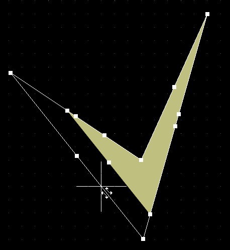
Sliding the edge of the Region to enlarge it.