Drill Table
Parent page: Objects
The Drill Table presents a live summary of all drill holes present in the board.
Summary
A standard element required for manufacture of a Printed Circuit Board is a drill drawing table, also known as a drill table or a drill drawing legend. The drill table lists the size and number of holes for each drill used on the board. Each drill size can be represented by a symbol, a letter or the actual hole size. When a drill drawing is generated for the board, each actual drill site is marked by a symbol, as shown in the image below. The Live Drill Drawing table updates in real time - as hole-containing objects such as pads and vias are placed on and removed from the PCB design, the table updates.
Availability
A Drill Table can only be placed in the PCB editor. Note that the drill table must be placed on the Drill Drawing layer, enable and select the layer prior to placement. To place a drill table:
- Click Place » Drill Table.
Placement
After launching the command, a drill table will appear attached to the cursor. Position the table in a suitable location outside the board and click to place it.
Non-Graphical Editing...
The following methods of non-graphical editing are available:
...via an Associated Properties Dialog
This method of editing uses the following dialog to modify the properties of a drill table object.
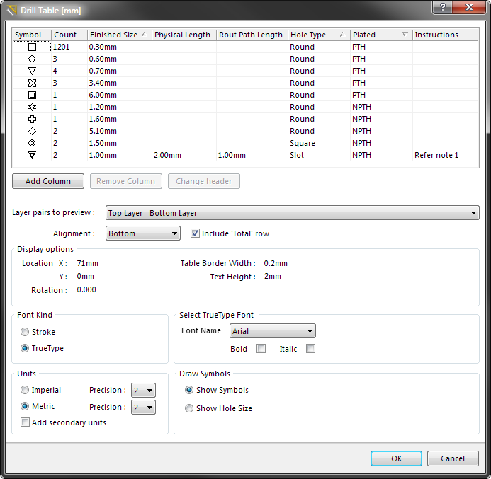
Edit the properties of the Drill Table in the dialog. Note the Instructions column, this is a user-defined column.
The Drill Table dialog can be accessed prior to entering placement mode, from the PCB Editor – Defaults page of the Preferences dialog. This allows the default properties for the drill table object to be changed, which will be applied when placing subsequent drill tables.
During placement, the dialog can be accessed by pressing the Tab key.
After placement, the dialog can be accessed in one of the following ways:
- Double-clicking on the placed drill table object.
- Placing the cursor over the drill table object, right-clicking and choosing Properties from the context menu.
Drill Table Sort Order
To sort the drill table, click the required column heading. A small triangle will appear, indicating the current sort direction - click a second time to reverse the sort direction. Multi-level sorting is supported, hold the Shift key as you click to sub-sort by a second (or third) column. In the image below the table has been sorted by:
- Plated (to separate plated from non-plated), then
- Hole Type (to order holes to Round then Slot then Square), then
- Finished Size (to order by size).

Sort the drill table by clicking the column headings, hold shift and click to sub-sort by other columns.
Customizing the Table
The drill table can be customized, including:
- Changing the column order - click and drag on a column header to change the order of columns.
- Change a column header - select the column then click the Change Header button, or right-click in the column and select Change Column Header from the menu.
- Hide a column - select the column then click the Remove Column button, or right-click and select Remove Column from the menu.
- Show a column - click the Add Column button then select the required column, or right-click and select the relevant Add Column menu entry.
- Add a Custom column - click the Add Column button then select Custom column, or right-click and select the Add Column » Custom Column menu entry. Both the header and the values are user-defined in a Custom column.
Layer Pairs to Preview
The drill table supports multi-layer boards that use layer-pair drilling. To support the designer in using the drill table during the design process the table includes the Layer pairs to preview option, set this to restrict the table to only show the drill holes for just the selected layer-pair. Note that the Layer pairs to preview option is not used to control which layer-pair drilling is included in the drill table during output generation, that is defined by the Drill Layers setting in the Layer Properties dialog in the output setup. That means that a single table can be placed on the design, the table will only include the appropriate layer-pair data during output generation of a drill drawing of that layer-pair.
Alignment
The table can be built from the bottom-up, Alignment = Bottom, or from the top-down, Alignment = Top. Use drthis setting to allow for table size changes without impacting on surrounding objects in the workspace.
Display Options
The drill table location can be precisely defined by configuring the Location X and Location Y settings if required. It can also be rotated if necessary. The grid lines in the drill table are actually Circuit Studio Line objects, use the Table Border Width to set the Line width.
Font Kind
Both Stroke and TrueType fonts are supported for text display in the drill table. Stroke fonts are native to Circuit Studio and are supplied as part of the installation. TrueType fonts obey the TrueType Fonts Save / Load Options configured in the PCB Editor - TrueType Fonts page of the Preferences dialog.
Units
Set the Units to Metric or Imperial, and the precision for each as required. Enable the Add secondary units option to display both types of units.
The Symbol that Represents each Hole Size
Each hole size can be represented by one of 3 styles of drawing Symbol:
- Symbol - draw a small geometric symbol at the location of each drill site. Note that a symbol is automatically chosen for each hole size, up to a total of 15 different sizes. These symbols tend to be open in their design, if a hole center marker is required include the Drill Guide layer in the output generation (as shown in the output image in the Notes section).
- Letter - draw a letter at the location of each drill site.
- Hole Size - draw the numerical size of the hole at the location of each drill site.
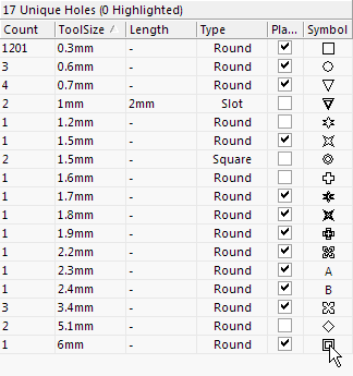
Configure the assignment of Symbol-to-hole size in the PCB Hole Size editor. The assignments are stored in the PCB file.
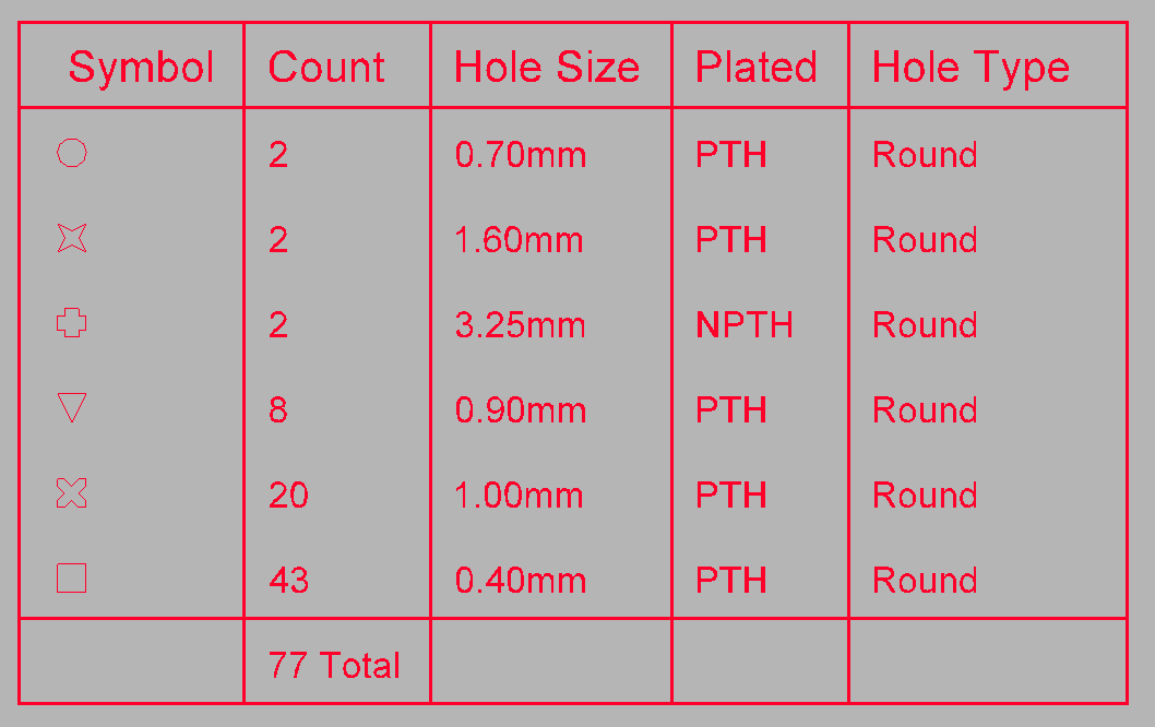
There is a total of 15 symbols available, as shown below. If there are more than 15 different hole sizes in the PCB then letters are automatically assigned.
![]()
The 15 pre-defined symbols that are available.
...via an Inspector Panel
An Inspector panel enables the designer to interrogate and edit the properties of one or more design objects in the active document. Used in conjunction with appropriate filtering, the panel can be used to make changes to multiple objects of the same kind, from one convenient location.
...via a List Panel
A List panel allows the designer to display design objects from one or more documents in tabular format, enabling quick inspection and modification of object attributes. Used in conjunction with appropriate filtering, it enables the display of just those objects falling under the scope of the active filter – allowing the designer to target and edit multiple design objects with greater accuracy and efficiency.
Graphical Editing
Moving a Drill Table
Click and hold anywhere within the drill table, then move it to a new location in the PCB editor workspace.
Interactively Resizing a Drill Table
The drill table is automatically sized based on the specified Text Height setting, as well as the number of different hole sizes (rows) and the number of defined columns. To interactively resize the table, click once to select it, then click and hold on a corner vertex. The Confirm dialog will appear, reporting that the table is locked, click Yes to continue and resize the table. Note that interactively resizing the table will also increase the font size.
Interactively Switching the Layer Pair to Preview
When the board includes layer-pairs, the displayed layer-pair is controlled by the Layer pair to preview option in the Drill Table dialog. This chosen layer-pair can also be switched using the PCB editor right-click menu, simply right-click on the drill table and select the required layer-pair in the Drill Table sub-menu.
Notes
The drill table will appear on all output that includes the Drill Drawing layer in it. The image below shows an example of drill drawing output, showing each drill site marked by the symbol that has been assigned to that hole size. This output also include the Drill Guide layer, which adds a small cross at each hole site.
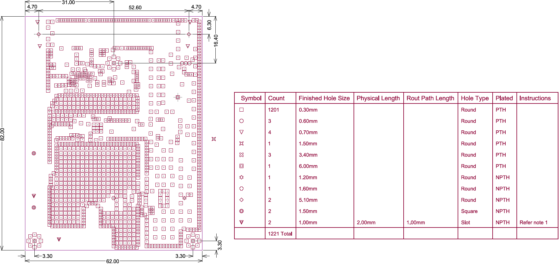
Example output of the Drill Drawing layer showing the Drill Table next to the board, with each drill site marked by the appropriate hole size symbol.