Custom Local Grid
Parent page: Objects
Cartesian and Polar-based local grids.
Summary
User-defined Cartesian and/or Polar-based local grids can be used to place design objects – especially components – with greater precision. Each grid-type is fully customizable using a dedicated editing dialog. Define where in the workspace the grid is to be located, the step size of the grid, the extent of the grid and two levels of visual display for the grid. In addition, a grid can be made available for use with component and/or non-component objects.
Availability&Placement
The user-defined grids can only be defined and managed from within the Grid Manager dialog.
Non-Graphical Editing
The following methods of non-graphical editing are available:
...via an Associated Properties Dialog
This method of editing uses the following dialog to modify the properties of a Grid object.
The Grid Manager dialog can be accessed in following ways:
Using the Grids command on the menu associated to the Snap button, at the bottom-right of the main design window.
- Using the G,M shortcuts.
- Using the Tools » Grid Manager command.
- Clicking the Grids button in the Board Options dialog.
- Using the View » Grids » Grid Manager command.
- Right-clicking in the workspace and using the Snap Grid » Grid Manager command.
Creating and Defining a Cartesian Grid
To create a new Cartesian-type grid use the Add Cartesian Grid command – available from the dialog's main menu or right-click menu – or press the R key. A new grid entry will appear in the list, initially with the default name New Cartesian Grid.
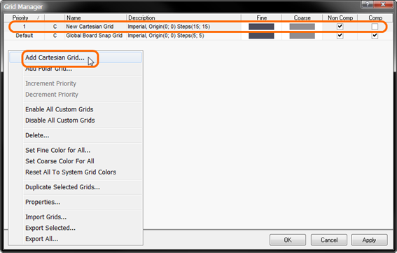
Example addition of a new Cartesian grid.
To edit the grid, simply double-click on its entry, or select its entry and use the Properties command accessible through the dialog's menus. The Cartesian Grid Editor dialog will appear presenting options with which to define the grid.
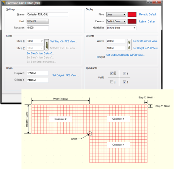
Example Cartesian grid definition, using the Cartesian Grid Editor dialog, and resulting appearance in the workspace.
Creating and Defining a Polar Grid
To create a new Polar-type grid use the Add Polar Grid command – available from the Grid Manager dialog's main menu or right-click menu – or press the P key. A new grid entry will appear in the list, initially with the default name New Polar Grid.
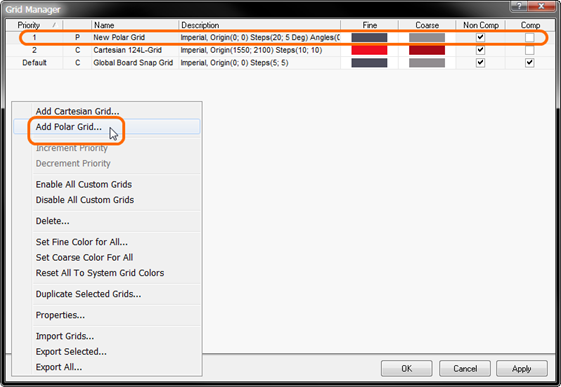
Example addition of a new Polar grid.
To edit the grid, simply double-click on its entry, or select its entry and use the Properties command accessible through the dialog's menus. The Polar Grid Editor dialog will appear presenting options with which to define the grid.
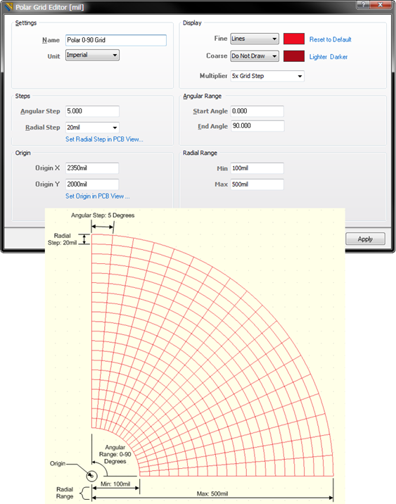
Example Polar grid definition, using the Polar Grid Editor dialog, and resulting appearance in the workspace.
Default Snap Grid
A default snap grid is defined for the board, named Global Board Snap Grid. This is the grid that is used for object placement and movement in any area of the board not covered by a dedicated local grid.
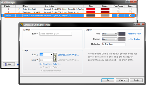
Global Board Snap Grid – used by default wherever no customized local grid is present.
The default grid is a Cartesian-type grid. The step size and/or display for the grid can be modified, but the grid cannot be renamed, disabled, or deleted.
Duplicating a Grid
To aid the designer in quickly building a set of local grids, the Grid Manager dialog supports the ability to duplicate grids. Simply select one or more custom grids in the existing list of grids and use the Duplicate Selected Grids command from the dialog's menus. Exact copies of those grids are created and added to the list, distinguished by the suffix (Copied) in their name.
Defining Grid Purpose
A defined local grid can be used in a variety of situations:
- In the placement of non-component objects only.
- In the placement of components only.
- In the placement of both non-component objects and components.
Definition of how a grid can be used – its purpose or application – is performed using the Non Comp and Comp checkboxes, associated with that grid's entry in the Grid Manager dialog. Use these checkboxes to determine how a custom local grid is to be used, for non-components and/or components, as required.
Defining Grid Display
For any custom grid defined, as well as the Global Board Snap Grid, options are provided to control how the grid is presented visually in the workspace. Two levels can be defined – Fine and Coarse. The fine-level display grid is used when zoomed-in. The grid markers for this level of grid display follow directly the defined step sizes for the grid. The optional coarse-level display grid comes into play when zooming out. The grid markers for this level of grid display are based on a specified multiple of the defined step sizes.
When choosing a color for this level of grid, a completely different color to that used for the fine-level display grid can be used. Alternatively, quickly employ a lighter or darker shade of the color currently used for the fine-level display grid, using the available Lighter or Darker links respectively.
Although individual grid display coloring is defined when editing a grid in the specific grid editor, a single nominated color can quickly be assigned for the fine- or coarse-level display grids – on a global level to all defined grids, including the default grid – from within the Grid Manager dialog. To do this, simply use the Set Fine Color for All or Set Coarse Color for All commands from the dialog's menus, then choose the required color from the subsequent Choose Color dialog.
Nesting and Grid Priority
Grids defined in the Grid Manager dialog can be freely stacked within the board area. By specifying origin coordinates accordingly grids can be overlapped, creating a nested hierarchy of grids, with which to fine tune placement of design objects during board layout.
Grid contention – which grid in an overlapping stackup of grids should a design object snap to – is resolved using a priority system. Each local placement grid created and defined is given a numbered priority. By default, each new grid is given the highest priority of 1, with all existing grids moved down in priority accordingly.
In the workspace, priority is distinguished by drawing order. The highest priority grid (priority 1) will be drawn in front of all other grids, then the grid with priority level 2, and so on, down to the default Global Board Snap Grid, which is drawn behind all other custom grids.
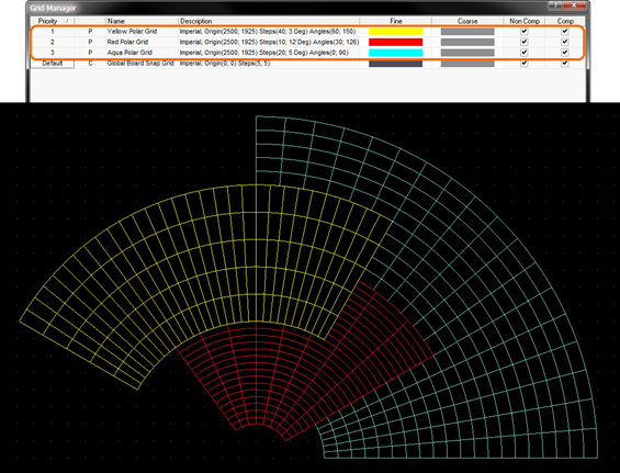
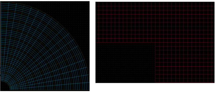
An example of three nested Polar grids. The Yellow Polar Grid has the highest priority and appears on top. The Red Polar Grid is next priority, appearing behind the yellow grid, but in front of the aqua grid. The default grid appears behind all of these grids, as all custom grids take precedence over it in the priority stakes.
Change the priority for a grid by selecting it in the list and using the Increment Priority and Decrement Priority commands (available from the dialog's menus) as required. A number of keyboard shortcuts are also available for setting the priority:
- U or Ctrl+Up Arrow – increase the priority of the focused grid.
- D or Ctrl+Down Arrow – decrease the priority of the focused grid.
- H or B – make the currently focused grid the highest priority (i.e. 1).
The priority of the Global Board Snap Grid cannot be changed – it is fixed to always have the lowest priority.
Disabling a Grid
There may be occasion where a grid isn't needed while placing or moving a particular design object. Rather than deleting the grid – it may be needed again later, in the same or different area of the board – it can simply be 'hidden' from the workspace. This can be achieved by un-checking the grid's associated Non Comp and Comp attributes in the Grid Manager dialog.
The Non Comp attribute can be quickly toggled for the focused grid using the Spacebar. In addition, commands available from the dialog's menus allow the designer to quickly Enable All Custom Grids or Disable All Custom Grids respectively.
Exporting and Importing Grids
The Grid Manager dialog provides controls for exporting and importing defined grids, so that preferred grids can always be accessed and used across different designs. Grid information is stored in a PCB Grid file (*.PCBGrid).
To export specific grids, select the grids and use the Export Selected command from the dialog's menus. To export all grids, use the Export All command. Use the subsequent Save PCBGrid dialog to determine where, and under what name, the file is to be saved.
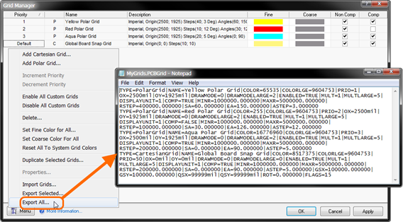
Example PCB Grid file, containing definitions for exported grids.
To import grids, simply use the Import Grids command from the Grid Manager dialog's menus. Use the Load Custom Grid dialog to browse to, and open, the required PCB Grid file. The grids will be added to the list of existing grids.
The ability to export and import grid definitions plays a valuable role in the PCB Library Editor domain, since grids defined in the Editor only apply to the current component. Simply define grids once, for a single component, then export them and import them to all other components as required.
Deleting a Grid
Custom grids can be deleted simply by selecting their corresponding entry in the Grid Manager dialog and using the Delete command from the dialog's menus. Remember that the default Global Board Snap Grid cannot be deleted.