Board Shape
Parent page: Objects
The Board Shape defines the shape of the finished board.
Summary
The board shape, also referred to as the board outline, is a closed polygon that defines the boundary, or extents, of the board. As well as providing a visual guideline of the extents of the space available for the placement and routing of the design, the board shape is also used by the internal power planes as the reference for the power plane edge pullback and the edge for splitting power planes.
Availability
The board shape is available only in the PCB editor. When a new PCB file is created it opens with a default 6 inch by 4 inch board shape.There are a number of ways this shape can be replaced or altered. The commands that are available for redefining the board shape depend on the current View mode.
View » Board Planning Mode, commands that support interactively changing the shape are available in this mode:
- Redefine Board Shape - select this command to interactively draw a new shape.
- Move Board Vertices - select this command to interactively modify the shape of the board by moving vertices or sliding the edges of the shape.
- Move Board Shape - select this command to move the complete board shape to a new location in the workspace. Note that this command only moves the board shape, other objects that have been placed in the workspace are not moved. To move the board shape as well as all placed objects, select everything to be moved and use the Edit » Move » Move Selection command (switch to 2D Layout Mode first).
View » 2D Layout Mode, commands for redefining the shape based on 2D objects are available in this mode (as well as commands to create objects from the shape), look in the Design » Board Shape sub-menu:
- Define From Selected Objects - select a set of line and/or arc primitives that define a closed shape, then select this command to redefine the board shape to match this shape.
- Create Primitives from Board Shape - Use this command when the board shape exists but there are currently no objects along the boundary
- Define Board Cutout - Use this command to interactively define a cutout on the board.
View » 3D Layout Mode, commands for redefining the shape based on 3D objects are available in this mode, the Design » Board Shape sub-menu:
- Define From 3D Body - select this command to define board shape by selecting the desired surface of a 3D model.
Redefining the Board Shape
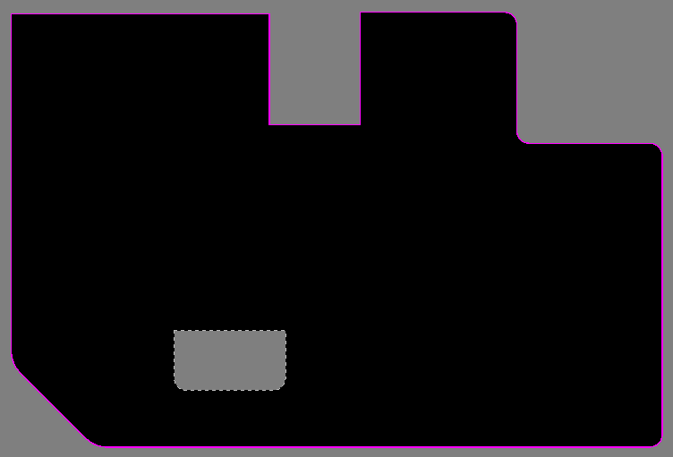
After launching the Redefine Board Shape command (in Board Layout Mode), the cursor will change to a crosshair and you will enter the standard polygonal object placement mode. Board shape definition is made by performing the following sequence of actions:
- Position the cursor and click to anchor the starting vertex for the board shape.
- Move the cursor ready to place the second vertex. The default behavior is to place 2 edges with each click (as shown in the first 5 images in the set below), with a user-defined corner shape between them. Refer to the Placement Modes topic below for more details on changing corner modes.
- Continue to move the mouse and click to place further vertices.
- After placing the final vertex, right-click or press Esc to close and complete the definition of the board shape. There is no need to manually close the board shape as the software will automatically complete the shape by connecting the start point to the final point placed.
Placement Modes
When redefining the board shape there are 5 available corner modes, 4 of which also have corner direction sub-modes. During redefinition:
- Press Shift+Spacebar to cycle through the 5 available corner modes: 45 degree, 45 degree with arc, 90 degree, 90 degree with arc, and Any Angle.
- Press Spacebar to toggle between the two corner direction sub-modes.
- When in either of the arc corner modes, hold the
 or keys to shrink or grow the arc. Hold the Shift key as you press to accelerate arc resizing.
 - Press the 1 shortcut key to toggle between placing 2 edges per click, or one edge per click. In this second mode the dashed edge is referred to as the look-ahead segment (as shown in the last image in the set below).
- Press the Backspace key to remove the last vertex.
Press Shift+Spacebar to cycle through the 5 available corner modes, press the 1 shortcut to toggle placement between 2 edges or 1 edge.
Graphically Editing the Board Shape
After launching the Move Board Vertices command (in Board Layout Mode) the polygonal outline of the existing shape will be displayed with a vertex at each corner and the center of each edge, and the cursor will change to a crosshair.
- Click and drag on a vertex to move that vertex. Note that doing this on a vertex that is in the middle of an edge will turn that single edge into 2 edges.
- Click and hold on a vertex, then press Delete to remove that vertex.
- Click and drag on an edge (away from a vertex) to move that edge of the board shape.
- Right-click or Esc to exit this editing mode.
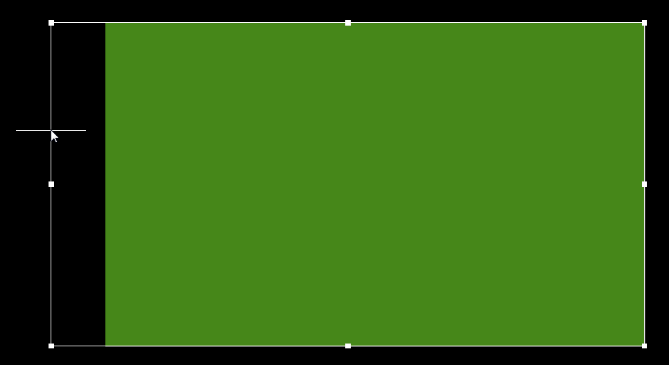
Sliding the edge of the Board Shape to enlarge it.
Defining the Shape from Selected Objects
The board shape can also be defined from selected objects in 2D Layout Mode. Typically this will be a set of lines and/or arcs placed on the Keepout layer, or a mechanical layer. Use the following sequence of steps:
- All the objects on a layer can be selected using the All on Layer command available on the menu at Edit » Select.
- Once all the objects are selected, run the Design » Board Shape » Define from Selected Objects command. The board shape will update to follow the path defined by the selected lines. A warning dialog will appear if the software is unable to follow the centerline of the selected objects (more below).
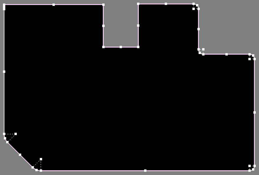
This Board Shape has been defined from a set of selected lines and arcs placed on the Keepout layer.
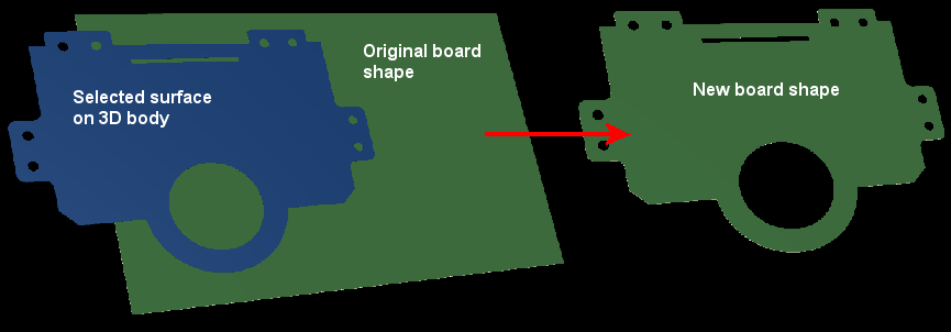
Define From 3D Body
This feature is accessed by selecting Design » Board Shape » Define from 3D body from the main menus [shortcut: D, S, S]. Prior to launching this command, you must have already placed a 3D body in the workspace and be in 3D mode for the command to be available. To define a board shape from 3D body:
- After launching the command, click the 3D body to select it, the cursor will change to a crosshair, ready to select the desired surface.
- Click on a flat surface of the STEP model - this surface will become the new board shape.
- Move the cursor around the model, when a surface is found, it is highlighted by the rest of the model being made somewhat transparent.
Creating Primitives from the Board Shape
As well as defining the board shape from selected primitives, it is also possible to create primitives from the board shape. Use this command when the board shape exists but there are currently no objects along the boundary. Situations where this command can be useful include:
- You want to modify the board shape (or board cutouts) by modifying track and arc primitives first
- You need a keepout boundary for the board, or keepout boundaries for board cutouts. This is discussed in more detail below in the Important Design Considerations When Using Board Cutouts section.
Cutting a Hole in the Board Shape
A board cutout can be placed anywhere in the board shape. To place a cutout:
- Click Define Board Cutout on the menu at Design » Board Shape. Note that the cutout is actually a Solid Region object configured to be a negative object, to learn more about placing one refer to the Solid Region object.
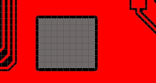
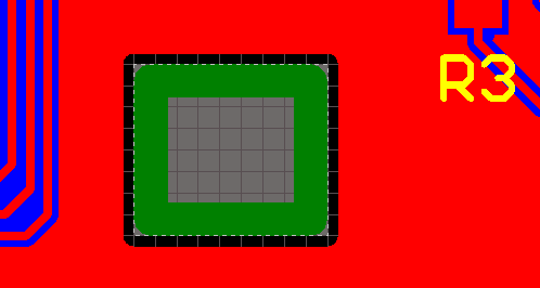
A Board Cutout has been placed on the Board Shape.
Important Design Considerations When Using Board Cutouts
Keeping the Polygon Back from the Edge of a Board Cutout
Polygons that overlay a solid region board cutout will pour as close to the edge of the cutout as allowed by the applicable Clearance design rule. A specific Clearance design rule can be created if required, which could for example be scoped to apply between IsBoardCutoutRegion and InPolygon.
Defining a Route Tool Path Around the Edge of the Board and Cutouts
A common approach used to cut the finished board from the fabrication panel is to mill or route the board out of the panel. Board cutouts can also be routed out. A Route Tool path is defined by placing Line and/or Arc objects on a mechanical layer. This can be done manually, or automatically by the software.
To define a Route Tool path for the board and any board cutouts:
- Run the Create Primitives from Board Shape command, available on the menu at Design » Board Shape. The Line/Arc Primitive From Board Shape dialog will appear.
- Define a suitable Width for the objects that will define the Route Tool path. Consult with your fabricator if you are unsure of this.
- Select an available mechanical layer, this layer should be reserved for just the Route Tool path definition.
- Enable the Include Cutouts option if the board has cutouts in it.
- Enable the Route Tool Outline option. When this option is enabled the line/arc objects are placed so their edge touches the edge of the board shape and the edge of the cutout.
- Click OK to create the Route Tool objects on the chosen mechanical layer.
- The mechanical layer used must be set as the Route Tool layer, to do this open the Board Options dialog (right-click in the workspace and select Options » Board Options) and select the required Layer in the Route Tool Path option.
The images below show the Route Tool path defined on a mechanical layer.
A Board Cutout shown on the left, with a Route Tool path defined in the image on the right.
Notes
- The board shape is not used for output generation, it is only the placed objects that are used.