Using Signal Harnesses
Contents
- The Objects of a Signal Harness system
- Signal Harness
- Harness Connector
- Harness Entry
- Harness Definitions
- How to Build a Signal Harness
- Step 1 – Defining a Harness Connector and connecting signals to it
- Step 2 – Creating Connectivity
- Advanced Topics
- Nested Signal Harnesses
- Nested Signal Harnesses and Harness Entries
- Nested Signal Harnesses and Harness Definition Files
- Nesting Multiple Instances of the same Harness Type
- Step 1 – Create Instances of the Stereo Signal Harness
- Step 2 – Nesting Multiple Instances of the Stereo Signal Harness
- Instantiations of the Same Harness Type and Harness Definition Files
- Identifying Signal Harness Instances
- Locking Harness Definitions
- How to Build a Harness – Advanced Methods
- How to Build a Harness using Harness Definition Files
- How to Build a Harness without a Harness Connector
- How to Build a Harness without a Signal Harness
- Extracting Individual Signals from a Signal Harness
- Troubleshooting
- Harness Definition Compiler Errors
- Net Mismatch Compiler Errors
- Syntactical Compiler Errors
The Schematic Editor has been enhanced to include the new concept of Signal Harnesses. Signal Harnesses enable the logical grouping of different signals including buses and wires, for increased flexibility and streamlined design.
Wires are used to represent an electrical connection between points, buses are used to represent a group of related signals which are identified by a specific naming convention.
Signal Harnesses on the other hand, involve the logical grouping of multiple signals including both wires and buses, this group can be treated as a single entity which can be used across your whole project. Signal Harnesses allow for the creation and manipulation of higher level abstract connections between subcircuits in your PCB Projects.
Signal Harnesses allow for a more complex design within the same schematic workspace thereby increasing readability of designs and building potential for re-use.
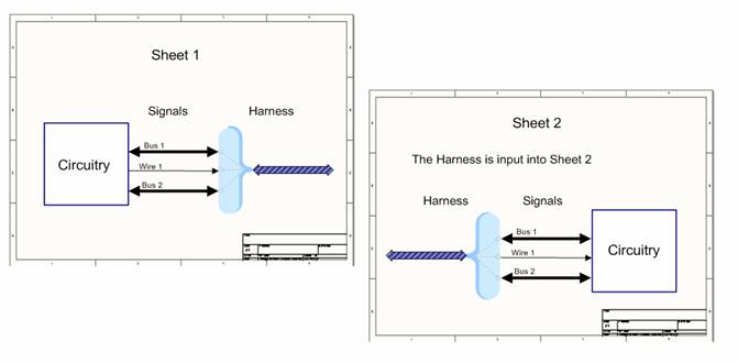
Figure 1: Harnesses consist of multiple signals which can include both wires and buses, grouped and then referenced as a single entity. The multi-wire connection is called a Signal Harness
The Objects of a Signal Harness system
There are 4 key elements to a Signal Harness system, accessible through the Schematic Editor:
- Signal Harness
- Harness Connector
- Harness Entry
- Harness Definition File
Signal Harness
This object represents the abstract connection which combines different signals. You can use this object to connect different subsystems across your design.

Figure 2: A Signal Harness links Sheet Entries
Harness Connector
This object is used to group various signals together in order to form a Signal Harness. It is both a graphical definition of the Signal Harness and a graphical means to include actual nets, buses and other harnesses to the main Signal Harness.
Figure 3: Harness Connector groups various signals. It is defined by the Harness Type which in this case, is I2S
Harness Entry
A Harness Entry is the graphical definition of a Signal Harness member. It is also the connection point through which actual nets, buses and Signal Harnesses are combined to form a higher level Signal Harness.
Figure 4: The Harness Entries are the graphical representation of the individual entries that are combined together and represented as a Signal Harness. In this case, the Harness Entries are WCLK, BCLK, DOUT, DIN and MCLK
Harness Definitions
Harness Definitions are formal textual definitions of Signal Harnesses. Each definition comprises of a Harness Type (in this case I2S) and Harness Entries (in this case: BCLK, DIN, DOUT, MCLK, WCLK). They are stored in text files called Harness Definition Files, identified by their extension * .Harness. Harness Definition Files appear in the Projects panel under the Settings\Harness Definition Files sub-folder. Altium Designer manages Harness Definition Files automatically.
Figure 5: The Harness Definition Files are text files that are located under Settings in the Projects Panel. These contain textual representations of Signal Harnesses and their respective Harness Entries. They can be identified by their extension * .Harness
The main design window has an icon that links directly to the Harness Definition File for your active Schematic Document. Click on ![]() button at the bottom right corner of your design window to display your respective Harness Definition File. Notice that this icon flashes red when you make any changes to Signal Harnesses, indicating that processing is occurring and your Harness Definition Files are being updated. You can also refresh your Harness Definitions by right clicking on the project file (*.PrjPCB) and selecting Regenerate Harness Definitions from the pop-up menu that appears.
button at the bottom right corner of your design window to display your respective Harness Definition File. Notice that this icon flashes red when you make any changes to Signal Harnesses, indicating that processing is occurring and your Harness Definition Files are being updated. You can also refresh your Harness Definitions by right clicking on the project file (*.PrjPCB) and selecting Regenerate Harness Definitions from the pop-up menu that appears.
How to Build a Signal Harness
A Signal Harness System is made up of a Signal Harness, Harness Connector, and Harness Entries. Connectivity between sheets is achieved by specifying a Harness Type on at least one Port or Sheet Entry across the Signal Harness.
In the following section, the use of Signal Harnesses, Harness Connectors, Harness Entries, Ports, Sheet Entries and Harness Types will be explained, detailing connectivity using Signal Harnesses across sheets. The following example demonstrates how to establish connectivity between sheets using a Signal Harness of Harness Type I2S.
Figure 6: A complete Signal Harness System is shown demonstrating how Signal Harnesses, Harness Connectors and Harness Entries complete the big picture.
Step by Step instructions are detailed below to help you understand how to build a complete Signal Harness System.
Step 1 – Defining a Harness Connector and connecting signals to it
Step 1 provides instructions on placing a Harness Connector and specifying the Harness Type, adding Harness Entries and then connecting signals to the relevant Harness Entries.
- Place a Harness Connector and specify a Harness Type by double-clicking on the object and populating the Harness Type field in the Harness Connector dialog, in this case I2S
- When this Harness Type is used within your project, the corresponding Harness Definition for this Harness Type is referenced
- Place the required number of Harness Entries and name them. The Harness Type and Harness Entries complete the Harness Definition
Figure 7: Step by Step graphical representations of placing a Harness Connector, placing Harness Entries and connecting signals to Harness Entries.
- Signals can now be connected to the Harness Entries.
Note: The Harness Type can be hidden from view or moved to save space in your design.
To hide the Harness Type either: - Double-click on the Harness Connector and enable the Hide Harness Type option in the Harness Connector Dialog
- Select the Harness Connector, open the SCH List and enable Hide Harness Type option
- Double-click on the Harness Type and enable Hide option.
- To move the Harness Type: Click on the Harness Type and drag it to your preferred position, pressing the SPACEBAR to change orientation. The Harness Type can also be placed inside your Harness Connector.
Step 2 – Creating Connectivity
Step 2 provides instructions for creating connectivity in your Signal Harness system by first adding a Signal Harness and then connecting to either a Port or a Sheet Entry. Next steps involve establishing connectivity between sheets by creating the complementary Signal Harness on the linked sheet.
- Connect a Signal Harness to the Harness Connector
- Connect the Signal Harness to either a Port or a Sheet Entry. Once a Port or Sheet Entry is connected to Signal Harness which is connected to a Harness Connector, the Harness Type of that Harness Connector is automatically populated and is inactive in the Port or Sheet Entry Properties. The I/O Type field is also automatically populated at this stage as Unspecified and is inactive.
- Name the Port or Sheet Entry, for example Audio I2S
Figure 8: Connectivity is established by connecting a Signal Harness and a Port to the Harness Connector.
The Harness Type for the port has been automatically populated with I2S and is inactive once it is connected to the Signal Harness and Harness Connector. This is the Harness Type defined for the Harness Connector in Step 1.
Once a Port or Sheet Entry is connected to a Signal Harness, you will notice that the Port or Sheet Entry changes color to match the color of the Signal Harness. If you specify a custom color for the Signal Harness, the Port or Sheet Entry will change color automatically to match your custom selection.
If the Signal Harness is no longer connected to either a Port or Sheet Entry, the Port or Sheet Entries will revert back to their default color unless a Harness Type is specified in the Port Properties or Sheet Entry dialogs.
If you prefer your Port and Sheet Entries to maintain their default color instead of using the Signal Harness color, navigate to your Graphical Editing Preferences:
- Select the DXP » Preferences command which brings up the Preferences dialog
- Navigate to the Graphical Editing tab under the Schematic folder
- Disable the Sheet Entries and Ports use Harness Color checkbox and click OK.
Figure 9: Disable the Sheet Entries and Ports use Harness Color field to force Sheet Entries and Ports to use their default color when they are connected to a Signal Harness.
To establish connectivity at the Sheet Level:
- Place Sheet Symbols and Sheet Entries, connecting the Sheet Entries together using a Signal Harness
- Name the Sheet Entries in Sheet Entry Dialog
- In the Sheet Entry dialog, select the Harness Type, I2S from the drop-down list. The Harness Type needs to be defined for at least one of the Sheet Entries connected by a Signal Harness.
The Sheet Entries are labeled Audio I2S, matching the Port names on the respective sheets.
Figure 10: The Signal Harness is now completely defined at the Sheet Level.
Alternatively, you can create a sheet symbol from an existing schematic document by:
- Right-clicking in your document and selecting Sheet Actions » Create Sheet Symbol From Sheet Or HDL and choosing which document to place
- Choose the schematic document with the Signal Harness created in Steps 1 and 2
- The created Sheet Symbol will have a port named Audio I2S with the Harness Type, I2S and I/O Type set to Unspecified.
To complete connectivity between sheets:
- Place a Port on the second sheet and select the name Audio I2S in the Port Properties dialog
- Place a Harness Connector, Signal Harness and Harness Entries corresponding to the Harness Entries created on PB01_ExtenderPlug.SchDoc. Alternatively, you can Copy and Paste your existing Signal Harness
- Select the Harness Type I2S from the Harness Type drop down list in the Harness Connector dialog. At this stage, the Harness Type for the port is automatically populated with I2S and is inactive.
Figure 11: Full connectivity is established by creating a Signal Harness with a corresponding Harness Type and matching Harness Entries.
Alternatively, you can use the Smart Paste feature to create Harness Connectors with Signal Harnesses with or without a port and specify the Harness Type and Port Name.
Advanced Topics
Nested Signal Harnesses
Signal Harnesses can contain nested Signal Harnesses, this means that a Harness Entry can be connected to another Signal Harness. This flexibility enhances the feature to a new level, further streamlining your design.
Nested Harnesses are useful when you have a very complex project that requires logical grouping of numerous signals. Signal Harnesses can be combined together to create a larger and more complex Signal Harness, while still allowing for re-use of smaller Signal Harnesses.
Figure 12: A Harness Entry may be connected directly to other Signal Harnesses.
Nested Signal Harnesses and Harness Entries
When a Harness Entry is connected to a Signal Harness, the Harness Type for that Harness Entry is automatically populated and is inactive. This field is populated by the Harness Type of your nested Signal Harness.
Figure 13: Harness Entry dialog showing the Harness Type, automatically populated and inactive. The Harness Entry Name is LineIn and the Harness Type has been automatically populated by the nested Harness Type, Stereo.
Nested Signal Harnesses and Harness Definition Files
A nested Signal Harness is represented like any other Harness Entry in the Harness Definition File with the exception of having curly braces, indicating a connection to a Signal Harness. In the example, the Harness Type is Audio_IO with Harness Entries:{LINEIN:Stereo},{LINEOUT:Stereo} and MICIN. The curly brackets are automatically generated in the Harness Definition File for nested Signal Harnesses.
Nesting Multiple Instances of the same Harness Type
The same Harness Type can be used multiple times in your design. This is useful when identical groups of signals are used differently in the design.
An example of this is the Stereo Signal Harness which is made up of identical signals with one instance used for LineIn and the other instance used for LineOut. Instead of creating two different Signal Harnesses, we can create one and re-use it, using Harness Entry names to distinguish between the nested instances.
Step 1 – Create Instances of the Stereo Signal Harness
- Create the Signal Harness of type, Stereo with Harness Entries, R, L with signals for LineOutR, and LineOutL labeled using net labels.
- Create another instance of the Stereo Signal Harness Type. You can copy and paste the existing Signal Harness, renaming the net labels where appropriate. In this case, the signals are labeled LineInR and LineInL
Note: Different net labels can be used on individual wires or buses in instances of the same Harness Type as these do not affect the Harness Definition.
Step 2 – Nesting Multiple Instances of the Stereo Signal Harness
- Connect the instances of the Stereo Signal Harness to the parent Harness Connector. The Harness Entry Names need to be unique to distinguish between the two instantiations of the same Harness.
Figure 14: Two instances of the same Stereo Signal Harness are used. The Harness Entry names distinguish between the different instances.
Instantiations of the Same Harness Type and Harness Definition Files
The Harness Definition File for Figure 13 shows the Harness Type is Audio_IO with Harness Entries:{LINEIN:Stereo},{LINEOUT:Stereo} and MICIN. The naming convention for instantiations of the same Harness Type is {HARNESSENTRYNAME:HarnessType}so in this case, there are two instantiations of the Stereo Harness Type, LINEIN and LINEOUT. The curly brackets are automatically generated in the Harness Definition File for nested Signal Harnesses.
Identifying Signal Harness Instances
Instances of Signal Harnesses can be created at any level in the project. In the examples used so far, Signal Harness Instances are not identified. This means that the names of the nets they contain have no relationship with the Signal Harness instance name.
Signal Harness Instances can be uniquely identified using net labels. Normal net naming conventions apply. If 'Higher Level Names Take Priority' is selected under Project Options, the net labels used on higher sheets in the hierarchy will be used to name the nets on the lower sheets. This naming convention applies with Signal Harnesses.
Figure 15: Two instances of the same JTAG_CONFIG Signal Harness Type are used. The Harness Type is defined in at least one of the ports across the Signal Harness. Net Labels have been used to associate the instance of the Signal Harness with the nets contained within them.
The instance names are used to associate the instance of the Signal Harness with the nets contained within them. This can be seen when using the Interactive Navigator in Altium Designer. In this example, the nets of the CONFIG_A instance of the JTAG_CONFIG Harness type will have the following naming convention:
- InstanceName.HarnessEntryName eg CONFIG_A.DETECT
or in the case of the Nested Harnesses: - InstanceName.HarnessEntryName.HarnessEntryName eg CONFIG_A.HARD.TDI
Figure 16: From Figure 14, all net labels in this sheet are given the prefix CONFIG_A. Interactive navigation with net labels expanded shows how the net labels are now associated with the Signal Harness Instance name.
Locking Harness Definitions
Harness Definitions are automatically generated when a Harness Connector is constructed with Harness Entries. When the Harness Connector is modified, the corresponding Harness Definition is updated to reflect the modifications.
The Harness Definition can be protected by manually locking the Harness Definition. This means that the Harness Definition will not be updated when the Harness Connector is modified, any new Harness Entries added to the schematics will not be added to the Harness Definition.
A Harness Definition can be locked by typing Locked; before each Signal Harness Definition.
If a Harness Definition is locked and a new Harness Entry is added to the graphical representation, the violation, Conflicting Harness Definition will be displayed on compilation. See the section, Troubleshooting for further information.
How to Build a Harness – Advanced Methods
How to Build a Harness using Harness Definition Files
Once the graphical representation of a Harness has been defined in the Harness Definition Files, a Signal Harness System can be built using the Place » Harness » Predefined Harness Connector command.
Harness Definitions are automatically generated when a Harness Connector is constructed with Harness Entries. When the Harness Connector is modified, the corresponding Harness Definition is updated to reflect the modifications. The list of Predefined Harness Connectors in the Place Predefined Harness Connector dialog includes all the of placed Harness Types in your project, all of the Harness Types defined in all open projects and a list of Harness Types defined in your Device Sheets folder (if you have declared Device Sheets in your Schematic Preferences). By default, the Place Predefined Harness Connector dialog is opened with your current project expanded.
You can also add predefined Harness Connectors at a textual level by modifying the Harness Definition Files. To do this:
- Open a Harness Definition File in your project
- Enter the details for your Harness Connector using the following syntax:
Locked;HarnessType=HarnessEntry1,HarnessEntry2,HarnessEntry3... - Nested Harnesses can also be defined in this way using the following syntax:
Locked;HarnessType={HARNESSENTRYNAME1:HarnessType},{HARNESSENTRYNAME2:HarnessType},HarnessEntry3...
You need to manually type in the curly brackets to indicate the Nested Harness.
Note: Harness Connectors defined textually require the Locked; syntax. If this definition is not locked, the changes will not be saved as Altium Designer manages the Harness Definition Files automatically based on graphical instances of Harnesses.
- Save the Harness Definition File
- Place predefined Harness Connectors in your project using Place » Harness » Predefined Harness Connector command or right-clicking in your schematic document and choosing Place » Harness » Predefined Harness Connector command from the pop-up menu that appears
- The Place Predefined Harness Connector dialog appears with a list of all available Harness Connectors in your current and open projects and in your declared Device Sheet folder. By default, your current project is expanded, showing Harness Connectors which can be further expanded to display the Harness Entries. In this dialog, you can choose to add and name a port of specified width and to add a Signal Harness of specified width.
Figure 17: The Place Predefined Harness Connector dialog. The current project is expanded showing all of the Harness Connectors in your project. All open projects are also listed as well as your declared Device Sheet folder.
- Once you select an existing Harness Connector to place, the Port Name is automatically populated with the Harness Type. You can customize your Port Name if you prefer by typing directly into the field.
Figure 18: The Place Predefined Harness Connector dialog. The I2S Harness Connector has been expanded, showing the Harness Entries. Notice how the Port Name has been populated with the Harness Type, I2S.
Figure 19. The JTAG Config Harness Connector is shown with the two nested Harnesses of type JTAG, with the harness Entries called Hard and Soft respectively.
- Predefined Harness Connectors with nested Harnesses will be built in the same way as other predefined Harness Connectors, with the exception of the Harness Entries having their Harness Type populated as per the Harness Definition.
How to Build a Harness without a Harness Connector
Once a Harness has been defined in your project, either graphically or textually, a Harness can be built without a Harness Connector.
In the JTAG_CONFIG Harness Type, there are 3 Harness Entries, HARD, SOFT (both of Harness Type, JTAG) and DETECT. In previous examples, this Signal Harness is represented as follows:
Figure 20: A fully expanded Signal Harness with Nested Harnesses.
To build this Harness without the JTAG_CONFIG Harness Connector:
- Define the JTAG_CONFIG Harness Type by either typing it manually in the Harness Definition File or having a graphical instance of it in your project. Ensure that Harness Definitions typed manually into the Harness Definition File are preceded with Locked; to ensure changes are saved
- Place a Port and select the name JTAG_CONFIG in the Port Properties dialog and connect a Signal Harness
- Add a net label to your Signal Harness, for example A, ensuring the Port connected to the Signal Harness has the Harness Type, JTAG_CONFIG in the Port Properties dialog
- Place the Harness Entries defined for the JTAG_CONFIG Harness Connector, in this case, two nested JTAG Signal Harnesses and a JTAG_DETECT wire. The Harness Entries require net labels using the syntax: A.HARNESSENTRYNAME to associate them with the Signal Harness. In this case, the Harness Entries will be named A.HARD, A.SOFT and A.JTAG_DETECT respectively.
The resultant Harness is shown below:
In the example shown above, we still have two nested JTAG Harness Connectors. This example can be further refined by removing the JTAG Harness Connectors.
Building on the above example, the steps to remove the JTAG Harness Connectors are:
- Define the JTAG Harness Type by either typing it manually in the Harness Definition File or having a graphical instance of it in your project. Ensure that Harness Definitions typed manually into the Harness Definition File are preceded with Locked; to ensure changes are saved
- Remove the JTAG Harness Connectors
- Rename the signals to A.HarnessType.HarnessEntryName for each of your signals to associate them with the nested JTAG Signal Harness and the JTAG_CONFIG Signal Harness.
The resultant Harness is shown below:
How to Build a Harness without a Signal Harness
A Harness Connector can be connected directly to a Port, Sheet Entry or Harness Entry. This means the Signal Harness is optional in your design. Removal of the Signal Harness from your design can save space and allow for a more complex design in the same workspace.
The JTAG_CONFIG Harness is shown below with Signal Harnesses removed.
Extracting Individual Signals from a Signal Harness
Individual signals in a Signal Harness can be extracted and referenced singularly in your project. To reference individual signals in a Signal Harness:
- Add a net label, for example, A to the Signal Harness you would like to extract individual signals from
- Place a wire and a net label and connect to either a Sheet Entry or a Port. Double click on the net label. In the Net Label dialog, type A. and all of the signals in the Harness will be displayed. In the dropdown. Choose your signal and click OK.
- The Interactive Navigator shows the signal A.JTAG_DETECT is connected to the Signal Harness, A.
Troubleshooting
There are a number of violations related to the placement of Signal Harness Objects in your project. The following information describes the violations as seen on your Schematic Document, the reasons for their occurrence and a resolution. To learn more about violations relating to Harnesses including violations reported in the Messages panel, please refer to the Project Compiler Error Reference.
Harness Definition Compiler Errors
Violation: Missing Harness Type on Harness
Reason: A Signal Harness connecting Sheet Entries or connecting a Sheet Entry and a Port is missing a Harness Type
Resolution: Specify a Harness Type across the Signal Harness for at least one of the objects.
Violation: Unknown Harness Type
Reason: A Harness Type is found but a matching definition cannot be found in a Harness Definition file. This can happen for one of two reasons:
- A Signal Harness is connected to an object (Sheet Entry, Port or Harness Entry) with an unknown Harness Type
- When a Harness Entry in a Harness Definition file refers to an unknown Harness Type
Resolution: Ensure that Sheet Entries, Ports and Harness Entries have a known Harness Type and Harness Definitions are accurate.
Violation: Conflicting Harness Definition
Reason: There are conflicting Harness Entries for the same Harness Type either at a graphical or textual level
Resolution: Update the Harness Definition File to reflect the changes or remove the offending Harness Entry.
Net Mismatch Compiler Errors
Violation: Bus Object on a Harness
Reason: A Port, Sheet Entry or Net Label has a label in the form [X..Y] indicating a bus object
Resolution: Ensure the objects across a Signal Harnesses do not have labels using bus syntax.
Violation: Harness Object on a Bus
Reason: An object such as a Port, Sheet Entry or a Harness Entry has an associated Harness Type which represents a connection to a Signal Harness when it is placed on a bus
Resolution: Use correct naming conventions for wires, buses and Signal Harnesses.
Violation: Harness Object on a Wire
Reason: An object such as a Port, Sheet Entry or a Harness Entry has an associated Harness Type which represents a connection to a Signal Harness when it is placed on a wire
Resolution: Use correct naming conventions for wires, buses and Signal Harnesses.
Violation: Multiple Harness Types on Harness
Reason: There are multiple Harness Types defined across a Signal Harness
Resolution: Ensure the Harness Types specified in an object (a Sheet Entry, Port, Harness Connector or Harness Entry) across a Signal Harness are identical.
Syntactical Compiler Errors
Violation: Harness Connector Type Syntax Error
Reason: Occurs if the Harness Type has any invalid characters (such as [ ] { } . : ) or if the Harness Type is blank
Resolution: Ensure the Harness Connector Type does not contain special characters and is not blank.