True Variants
Contents
- Understanding Logical and Physical Components
- Types of Variations that can be Performed
- Fitted
- Fitted with Varied Parameter(s)
- Not Fitted
- Alternate Part
- Changing the Type of Component
- Variations that can not be Performed
- Multi-channel Designs
- Output Documents Affected by Variants
- Creating and Configuring a Variant
- Creating a New Variant
- Defining Component Variations
- Choosing an Alternate Part
- Varying Components in a Project that uses a DbLink File
- Managing the Display of Data in the Variant Management Dialog
- Configuring the Display of Variants on the Schematic and PCB Drawings
- Resetting and Updating Variant Data
- Updating a Varied Parameter
- Updating the Parameters in an Alternate Part
- Completely Updating the Component for an Alternate Part
- Updating or Resetting Multiple Parameters for Multiple Components
- Working with Variant Parameters
- Working With Variants in the Schematic Editor
- Examining Varied Components on the Schematic
- Compiling a Design with Alternate Parts
- Defining a Variation from the Schematic Sheet
- Working with Variants in the PCB Editor
- Alternate Parts and the PCB Design Process
- Stacked or Overlapped Alternate Parts and the DRC
- PCB Re-Annotation
- Working with Variants in the OutputJob Editor
- Varied Output Documents
- Configuring the BoM when there are Database Components
- Variant Errors

The ability to create variations of the same base design is a real strength of Altium Designer, and a tremendous productivity booster for designers. Using variants, you can define any number of variations of the base design, configuring each component to be: fitted; not fitted; fitted with modified component parameters, such as the component's value; or, with the release of Altium Designer 14.3, you can completely replace a component with an alternate part. Variants that use any of these types of variations are all referred to as Assembly Variants, as they only impact on the assembly process — all variants share the same fabricated bare board.
There is also support for variations to component overlay information on the PCB, for example changing a components comment. This type of variation requires 2 overlay screens to be produced, resulting in 2, different bare boards. This type of variant is referred to as a Fabrication Variant.
Along with the introduction of support for alternate parts, the Variant Management user interface has been updated and simplified. This article take a closer look at how you define and manage variants in Altium Designer 14.3.
Understanding Logical and Physical Components
In Altium Designer there are two types of components, logical components, and physical components. This distinction is important, as it underlies some of the most powerful features in Altium Designer. The components you place on the schematic sheet are logical components, each a conceptual entity that represents the actual component that is ultimately mounted on the assembled PCB.
While this one-to-one, logical-to-physical model works well for a simple design, it cannot support all of the design requirements needed by the electronic product designer today. Altium Designer supports powerful concepts like: multi-channel design, where a section of circuitry is stamped out as many times as you require; and variants, where a single design can be implemented with different components fitted to each variant of the board. Features like this require the ability for one logical component to represent multiple physical components.
Altium Designer delivers this one-to-many capability through its compiler technology. When you compile your logical design, each physical component is instantiated in memory, ready for transfer to the board design workspace.
Because there are situations where you, the designer, still need access to the physical components at the schematic capture stage, the physical design is also made available in the schematic editor. They are accessed via the extra tab(s) at the bottom of each schematic sheet. The left-most tab is the logical design you captured, the other tab(s), called the compiled tab(s), represent that chunk of physical design as it will be transferred to the PCB design workspace. Note that the schematic that is presented on the compiled tab cannot be graphically edited, for example you cannot modify the wiring, or move a component.
Types of Variations that can be Performed
Before you can create a variant, you first create the original design, which is referred to as the base design. Working from the base design, you then go through a process of configuring the components to be: Fitted; Fitted with varied parameters; Not Fitted; or to use an Alternate Part.
Fitted
This is the default state of a component, if it is Fitted, then it is not varied. When you create a new variant, all components default to Fitted. A component with a state of Fitted is represented in the Variant Management dialog as an empty cell — more on this dialog later.
Fitted with Varied Parameter(s)
A component can have any of its parameters varied, as part of the variant definition process. Modifying the value of a parameter is a local variation, only affecting the output documentation. The original schematic, and the component whose parameter is being varied, are not modified in any way. In the image below, C9 has the Value parameter varied, this variation is shown by displaying the Value using a green, italic font.
Not Fitted
If a component is set to Not Fitted, it still exists on the schematic and is transferred to the PCB, but it is removed from the appropriate output documentation, such as the BoM. You can configure how Not Fitted components are presented in the documentation, for example they can be marked with a cross on the schematic and in PCB drawing outputs.
C3 and C7 are fitted, C4 and C8 are not fitted, and C9 is fitted, with a parameter value varied.
Alternate Part
It is also possible to select an entirely different component, as an Alternate Part. Since the Alternate Part is a different component, only one or the other component is presented on the compiled tab of the compiled schematic sheet. There is also the requirement that the alternate part shares the same set of pins, placed in the same locations, as the base part. This is an essential requirement to ensure the connectivity remains valid when the design is compiled.
Q1 is an NPN transistor in the TSOP variant, and a JFET in the BGA variant.
There are two ways an Alternate Part is handled on the PCB:
- If the footprint is the same — if the chosen Alternate Part has the same footprint name as the base part, then only one instance of that footprint will be transferred to the PCB. As multiple footprints can be assigned to a component, you should ensure that the correct footprint is selected in the Variant Management dialog for each variant.
- If the footprint changes — if the chosen Alternate Part has a different footprint name from the base part, then both footprints are transferred to the PCB. As the designer you must then decide how to position the two footprints on the PCB. Note that both footprints will have the same designator, as only one or the other component is ever fitted.
Changing the Type of Component
The ability to select an alternate part is not restricted to choosing the same type of component, so you can, for example, have a base component that is a resistor, then define an alternate part that is a capacitor. It is important to be aware of the consequences of this type of alternate part:
- The designator - there is only 1 designator for each logical, base component, and it is this designator that is used for all variants. If you swap a resistor for a capacitor you might want to consider using a special designator prefix, for example
R_C, orR-C. - The pins - the alternate component must have the same number of pins as the base component, and these pins must be in the same location and of the same electrical type. A warning will appear if these conditions are not met.
Variations that can not be Performed
True variant support continues to be developed, as the needs of designers and their designs grow, and development resources permit. Currently, the following area is not supported for variants.
Multi-channel Designs
Main article: Multi-Sheet and Multi-Channel Design
Multi-channel design allows the designer to nominate a single schematic sheet or a tree of sheets, to be repeated - effectively stamping out this section of the design multiple times. Rather than copying and pasting, the software manages the stamping-out process, with the designer defining the annotation method used to identify the repeated components. The repeated channel is created by using the Repeat instruction in the appropriate Sheet Symbol field, or by instantiating multiple sheet symbols that reference the same child sheet.
At this stage, alternate part variations within the channel of a multi-channel design are not supported.
Output Documents Affected by Variants
Assembly variants affect all output documentation that include detail about the purchase or loading of components. This includes:
- Bill Of Materials
- Schematic Prints
- PCB Prints
- PCB 3D Prints
- PCB 3D Videos
- Assembly Drawings
- Pick and Place files
- Test Point Report
Fabrication variants also affect the following outputs:
- Gerber overlay layers
- ODB++ overlay layers
Creating and Configuring a Variant
Variants are created and configured in the Variant Management dialog, select Variants from the Project menu to open the dialog (shortcut: C, V). The dialog has 2 main regions:
- the upper region, titled Project Components, lists all of the components in the base design;
- the lower region, titled Parameter Variations, details all of the parameters of the component(s) currently selected in the upper region.

Variants are created and configured in the Variant Management dialog.
The Variant Management dialog has undergone a number of user interface improvements, to provide more information and make it easier to use.
Enhancements include:
- Additional columns - the dialog includes 2 new columns:
- Hierarchy Path, which details where to locate the physical instantiation of a component in the design hierarchy;
- Library Link column, which details where the base component was sourced from.
- Ability to hide/show columns - right-click on the column heading to display the context menu, use the options in the Columns sub-menu to hide/show columns.
- Clearer presentation of varied parameters - a parameter that is varied from the base design is shown in bold, making it easier to visually identify.
Creating a New Variant
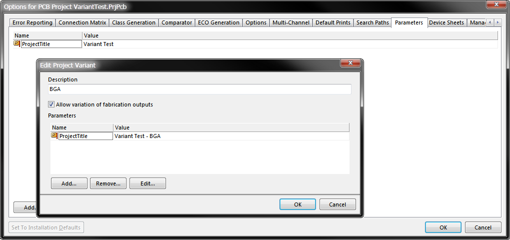
Click the Add Variant button in the Variant Management dialog to create a new variant of the base design. The Edit Project Variant dialog will open, enter a name for the variant in the Description field and click OK. The other options in this dialog are discussed in more detail later.
An additional column will appear on the right of the Variant Management dialog, with the just-added Variant name as the column title. All the cells will be empty, an empty cell indicates that this component is Fitted, and is unchanged from the base design. You are now ready to configure the components for the new variant.
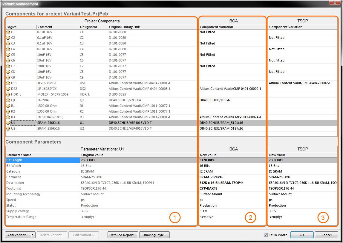
Region 1 in the image details the components in the base design, region 2 details the components in the variant called BGA, region 3 details the components in the variant called TSOP. Note the bold parameters, indicating that these parameters have different values from the base design.
Defining Component Variations
Once the variant has been created, you are ready to configure the state of each component. This can be done by clicking the component cell in the variant column to reveal the ![]() button, or by right-clicking to access the context menu commands. When the
button, or by right-clicking to access the context menu commands. When the ![]() button is clicked, the Edit Component Variation dialog will open, presenting you with 3 choices:
button is clicked, the Edit Component Variation dialog will open, presenting you with 3 choices:
- Fitted - the original component as used in the base design is also fitted/used in this variant of that design. For a newly added variant, all components are fitted by default. The cell for a fitted component is empty. Note that individual parameters can also be varied for a fitted component - simply type in the new parameter value - varied parameters are shown in bold.
- Not Fitted - the original component as used in the base design is not fitted/used in this variant of that design. For a Not Fitted component the cell displays the text Not Fitted.
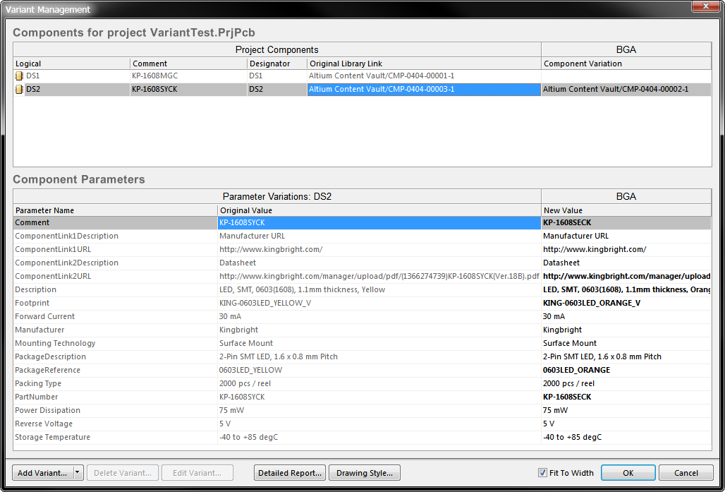
- Alternate Part - this option gives access to selecting the alternate part. Once chosen, the cell displays the alternate part's Library Link. The lower region of the dialog will display all of the parameters in the alternate part.
Choosing an Alternate Part
When you select Alternate Part in the Edit Component Variation dialog, the dialog expands to include controls used to browse and locate the required alternate part component. All of Altium Designer's component storage models are supported, such as independent libraries, database libraries, as well as vault-based components (as shown in the image below).
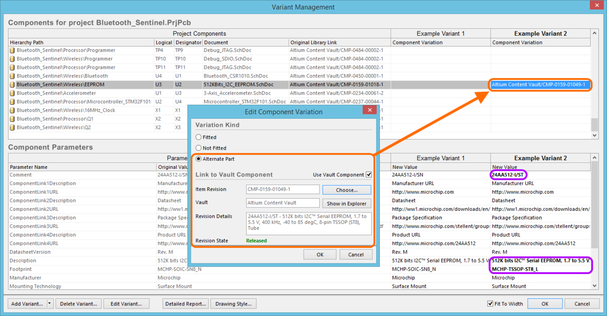
In this example the alternate part has been selected from the Altium Content Vault, note that each parameter that is different is highlighted in bold.
You can visually check the chosen alternate component back in the workspace. Switch to the compiled tab view for the applicable schematic sheet that the component is on, then select the required variant in the Variant toolbar dropdown. The Schematic Editor will use the symbol graphics for the chosen alternate component. If the component is pin-compatible and graphically similar, you should see very little change. In the image below, the tell-tale sign for the use of a different component is the different comment for the alternate part. Note the green italic font used for the alternate component, this is configured in the Variant Options dialog, click the Drawing Style button in the Variant Management dialog to open the dialog and configure how a varied component is displayed.
Verifying the compatibility of the chosen substitute component, graphically. In this example, Example Variant 1 uses the same component as the base design, while Example Variant 2 uses a different component, though it is identical in symbol graphics and is pin compatible with the original.
Varying Components in a Project that uses a DbLink File
Main article: Linking Existing Components to Your Company Database
Altium Designer supports a number of ways of storing and working with components. This includes using a DBLink file with the project. A DBLink file is an interface between the components on the schematic and a company database. Rather than referencing from each component to a specific database record (as is typically done when you place a component from a DBLib-type library), the DBLink model relies on the designer initiating a query action to check one or more component parameters, the software then searches the database for a record with fields that contain matching values. When a match occurs, other field values from that record, such as the Part Number, can be returned to the Altium Designer component. The component parameter-to-database field mapping is defined in the DBLink document, as is the target database.
In a standard design the query action is performed via the Update Parameters from Database command, and can also be performed during BoM generation by enabling the Include Parameters from Database option, to extract BoM-specific component data, such as price.
For a design that includes variants, the parameters used to query the database are varied in the Variant Management dialog. Since those parameter values only exist in the Variant Management dialog the Update Parameters from Database command is not used to retrieve database information, instead they are extracted from the database when the BoM is being generated. Refer to the section Configuring the BoM when there are Database Components for more information.
Managing the Display of Data in the Variant Management Dialog
The Variant Management dialog includes features to help control the amount of data displayed, use this to help when working on a large design.
- To remove columns that you are not interested in, right-click in upper part of the dialog and toggle the visibility of any column in the Columns sub-menu.
- To display only those components being varied, right-click in the upper part of the dialog and select Only Show Varied Components from the menu.
- After selecting the Only Show Varied Components mode, right-click again and configure the Filter options as required. In the image below, the Filter has been configured to only display components that use Alternate Parts.
- To change the order the variants are listed, click and hold on the column heading, then drag that column to a new location. Use this in combination with the Fit to Width checkbox to position and size the variant of interest in your preferred working location.
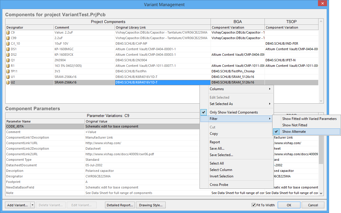
The Variant Management dialog, with columns hidden and a filter applied to only show components that use an Alternate Part.
Configuring the Display of Variants on the Schematic and PCB Drawings
As the designer you have control over the way in which varied components are presented on the schematic sheets (which then flows through to printed or PDF'd outputs), and in PCB drawing type outputs, such as assembly drawings. These are configured in the Variant Options dialog, as shown below. To access the dialog, click the Drawing Style button down the bottom of the Variant Management dialog.
Configure how the variants are presented on the schematic and in PCB drawing outputs, in the Variant Options dialog.
Resetting and Updating Variant Data
When you configure variations in the Variant Management dialog, the settings are saved in the project file. This includes the Not Fitted state, local parameter variations to a Fitted component, and the parameter values of Alternate Parts. The Alternate Parts are stored in the file <ProjectName>.PrjPcbVariants. The Variant Management dialog includes command for resetting parameters and updating components, to ensure you can keep them in sync with the source component libraries.
Updating a Varied Parameter
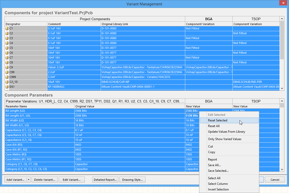
Parameters modified locally in the Variant Management dialog can be restored to their original value by right-clicking on the modified parameter in the Variant Parameter list (shown in bold), and selecting Reset Selected from the menu, as shown below. Note that you can multi-select and reset the value of multiple parameters in a single action, or alternatively, Reset All parameters for that component.
Modified parameters can have their value(s) restored using the Reset Selected command.
Updating the Parameters in an Alternate Part
If there are parameter changes made to a library component that is used as an Alternate Part, then you to can bring those changes directly into the variant definitions in your project by right-clicking in the Variant Parameter list and selecting Update Values from Library from the menu (as shown below). Note that this updates the parameters, if you need to update the graphic, use the technique described below.
If an Alternate Part component has been modified in the library, use the Update Values from Library command to refresh the copy used in your project.
After selecting the Update Values from Library command, you will be required to browse to and locate the component in the source library/Vault. Once this has been done, the Update Project Variants From Library dialog will appear, as shown below.
Updating a varied component from the source library, here you configure which parameters are updated, and to which variant the updates are applied.
On the left side of the dialog all parameters are listed, if required you can uncheck any parameter to exclude it from the update process. On the right of the dialog you select which Project Variants to Update, it will default to select the Variant over-which you performed the right-click to access the Update Values from Library command. Click OK to complete the update process.
Completely Updating the Component for an Alternate Part
As mentioned, components used as Alternate Parts are stored in a separate file, called <ProjectName>.PrjPcbVariants. If the source component for an Alternate Part has been edited in the library it can be updated by running the Update from Library Wizard. Launched from the Tools menu, the Wizard includes an option to Include Variants, when this is enabled the component list will expand to include any components that have been used as Alternate Parts. Complete the Wizard to update the required parts.

To fully update an Alternate Part, including the graphic, enable the Include Variants checkbox, then enable the part that is being updated.
Updating or Resetting Multiple Parameters for Multiple Components
The Variant Management dialog supports multi-select, this means you can select many or all components across many or all variants in the upper part of the dialog, and then perform parameter update actions on one or more parameters, for one or more components, in one or more variants.
As an example, you might want to reset the manually varied parameters for all components, in all variants.
To do this:
- Use the Only Show Varied Components right-click menu option, in combination with the right-click Filter options, to only Show Fitted with Varied Parameters. The upper part of the dialog should now display only those components that have manually varied parameters.
- Right-click in the upper part of the dialog again and choose Select All from the context menu. All components currently displayed in the upper part of the dialog will be selected.
- Now right-click in the lower part of the dialog and choose Select All from that context menu. All parameters for all components will now be selected. Note that you could have chosen the Select Column command instead, to only apply the Reset action to the components in a specific Variant.
- Right-click again in the lower part of the dialog, and choose Reset Selected from the context menu, as shown in the image below.
Resetting all manually varied parameters, for all components, in all variants.
Working with Variant Parameters
Altium Designer supports parameters at various levels of the project. For example, you can add document-level parameters to each schematic sheet in the Document Options dialog (Design » Document Options). You can also add project-level parameters to the project, in the Parameters tab of the Options for Project dialog (Project » Options). Parameters can also be added to a variant, in the Edit Project Variant dialog (Variants Management dialog, select the variant then click the Edit Variant button).
Parameters have a hierarchy, which means you can create a parameter with the same name at different levels of the project, each having different values. Altium Designer resolves this in the following way:
- Variant (highest priority)
- Schematic document
- Project
That means the parameter value defined in the schematic document overrides the value defined in the Project options, and the value defined in the variant overrides the value defined in the schematic document. Note that schematic-level parameters are not available on the PCB or in the BoM, for these types of output you should use project or variant parameters.
In the images below, a Parameter called ProjectTitle has been defined for the project, and also for each variant. The animation shows the behavior on the PCB as the Variant toolbar is used to show the base design, then each variant.
The special string .ProjectTitle was placed on the PCB overlay, which is automatically linked to parameters of the same name. Note how the value changes as the Variant is changed.
Working With Variants in the Schematic Editor
It is important during design capture that you have complete visibility of the component variations used in each variant. To support this, the schematic editor includes a number of features, as described below.
Examining Varied Components on the Schematic
As described earlier, to examine variant detail on the schematic you:
- Recompile the project if it is not already compiled.
- Select the compiled tab down the bottom of the schematic sheet.
- Select the required variant in the Variants toolbar dropdown.
- Components varied on this sheet will then be displayed, as configured in the Variant Options dialog.
Select the compiled sheet and the Variant (orange highlights), to view the components varied on this schematic sheet.
Compiling a Design with Alternate Parts
When you compile a design that includes a variant with Alternate Parts, Altium Designer must compile the design as if both components were present. This is to ensure that any issues are detected; so that the complete design, including both footprints, can be transferred to the PCB editor; and so that all data is available for variant output documentation. In the example below the Navigator panel shows U1 twice, and you can also see pin U1-6 appearing twice.
U1 has an alternate part used in a Variant, so appears twice in the Navigator panel.
Defining a Variation from the Schematic Sheet
It is often easier to work directly from the component(s) placed on the schematic sheet, rather than scrolling up and down through a list of components in a dialog. Simply select the component(s) on the sheet, then right-click and select Part Actions » Variants from the menu, as shown below.
2 LEDs have been selected on the schematic, use the right-click command to configure just those components in the Variant Management dialog.
The Variant Management dialog will open, displaying only the selected components. Perform the required variations and click OK to apply them to the design.
The Variant Management dialog has been opened from the schematic sheet, detailing just the 2 selected LED components.
Working with Variants in the PCB Editor
In the PCB editor, all of the component footprints, for all variants, are always shown. This is necessary because all footprints, for all assembly variants, must be fabricated as part of the bare board. It is the loading of components during the assembly process that then determines which variant is being built.
Because all footprints are always visible on the PCB, it can be difficult to know which components belong to which variant. The PCB editor includes a Variants toolbar which can be used to switch between variants. However the only visible clue to tell if a particular component is fitted or not fitted in that variant, is if the component includes a 3D Body, then that body will appear/disappear to indicate when the component is fitted or not fitted. This fitted/not fitted behavior can be seen much more easily when the PCB is in 3D Layout Mode, as demonstrated in the animated image below.
Alternate Parts and the PCB Design Process
There is only one type of variation that affects component placement in the PCB design process; when an Alternate Part is specified, and that Alternate Part uses a different footprint from the base design. In this situation you must place 2 footprints on the board.
How you position the 2 footprints is up to you, it could be that:
- the footprints are placed next to one another;
- the smaller footprint is placed inside the larger footprint, as shown in the animated image below where an SRAM component can be purchased either in a TSOP package or a BGA package;
- the footprints are exactly stacked (placed one on top of the other), for example when the footprints are identical but they have different 3D models, so must have different footprint names. This is also shown in the image below, where 2 LED footprints are stacked for both DS1 and DS2.
An animation showing how Alternate Parts, that use different footprints, can be positioned on the board.
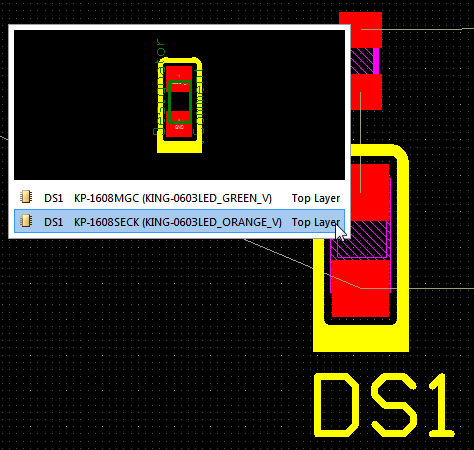
The 2 instances of LED DS1 use exactly the same footprint pattern, but have different 3D models in each variant, so can be stacked.
Stacked or Overlapped Alternate Parts and the DRC
If your design includes variants with Alternate Parts, you will end up with multiple instances of the Alternate Parts on the PCB, one for each variant. If they are going to be stacked or overlapped, like the LEDs and SRAM components shown in the images above, you should set up a Component Clearance design rule to prevent the stacked components creating a violation. An example of how this was done for the two DS1 LEDs in the image above, is shown below.
A Component Clearance design rule that will allow the two DS1 LEDs to be stacked.
PCB Re-Annotation
Performing a PCB re-annotation is a popular requirement for many designers, to ensure that components can easily be located on the board. This release sees the introduction of support for alternate parts, like all other components, the alternate parts have their designators re-assigned when a positional re-annotation is performed, but the alternate parts still have the same designator as each other. These annotation changes can be pushed back to the schematic.
Working with Variants in the OutputJob Editor

An OutputJob where the outputs for both variants have been set up.
There are 2 approaches to configuring your OutputJob file to support variants. You can either:
- configure the entire OutputJob to use a specific variant, by selecting the Choose a single variant for the whole OutputJob file option at the top of the OutputJob editor, and then select the required variant in the dropdown, or
- configure each Job in the OutputJob file to use the variant selected in the Variant dropdown for that Job.
If you choose the first approach, then every output file that is variant-specific will automatically be configured for that variant. The advantage of this approach is that you do not need to specifically select the variant, the disadvantage is that you will need an OutputJob file for each variant.
Varied Output Documents
As mentioned earlier, assembly variants affect all output documentation that includes detail about the purchase or loading of components. This includes:
- Bill Of Materials
- Schematic Prints
- PCB Prints
- PCB 3D Prints
- PCB 3D Videos
- Assembly Drawings
- Pick and Place files
- Test Point Report
Fabrication variants also affect the following outputs:
- Gerber overlay layers
- ODB++ overlay layers
Configuring the BoM when there are Database Components
The BoM dialog inlcudes 2 options that are used with designs that include components linked to a database. Both DbLib and DbLink database linkage methods are supported.
- Include Parameters from Database - Query the database and include parameters defined in the DbLib or DbLink. Database parameter values will override design parameter values.
- Include in Component Variations - also include parameter updates for components varied in the Variant Management dialog.
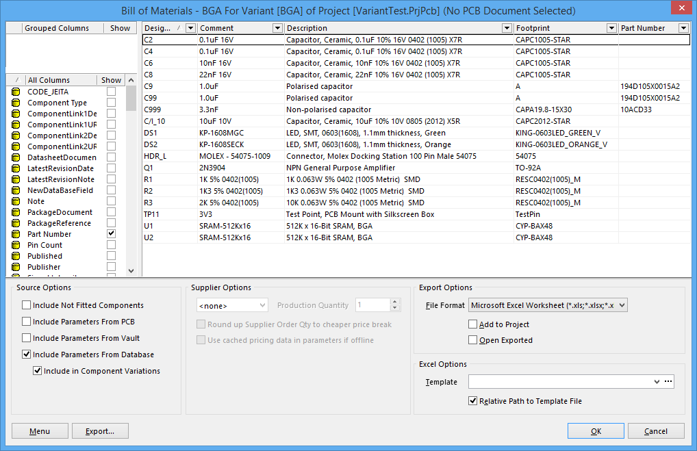
Enable the Include Parameters from Database option to include database information and update the design parameters.
Variant Errors
Variant settings are stored in the project file (*.PrjPcb). When the Variant Management dialog is opened, this data is read and analyzed, then loaded into the Variant Management dialog. If there are issues detected during data loading, such as mismatches between component designators or component UIDs, an Information dialog will open outlining the problem, as shown in the image below.
Component UID mismatches are automatically resolved, simply close the dialog and save the project to retain these corrections. Duplicate designators must be resolved at the schematic level, recompile the project and check the Messages panel for warning/error details to resolve these.
Resolve designator and UID mis-matches before continuing with the design process.