Rule Definition for Differential Pair Routing
Contents
Differential pair routing is a design technique employed to create a balanced transmission system able to carry differential (equal and opposite) signals across a printed circuit board.
Main article: Differential Pair Routing
Simplified Differential Pair Routing Rule Definition
The Differential Pair Routing rule is used to define the routing width of each net in the pair, and the clearance between the nets in the pair.
The settings defined in the applicable Differential Pair Routing rule are used:
- During interactive routing of the pair
- During interactive re-routing of the pair
- When interactively modifying the pair, such as sliding a track segment of one of the nets in the pair.
During design rule checking, the following rules are applied:
- Width of each net in the pair - applicable Differential Pair Routing rule
- Clearance between the nets in the pair - applicable Clearance rule
Note that the clearance from a net in a differential pair to any other electrical object that is not a part of the pair is also monitored by the applicable Clearance rule.
For a differential pair the Width and Gap settings can either be set for all layers using the controls beside the image of the pairs, or they can be set for each layer in the grid region below the image.

Both the routing width and the pair gap are defined as part of the Differential Pairs Routing rule.
Interactively Switching the Differential Pair Width-Gap Settings
A common requirement during differential pair routing is the need to change the routing width, for example to neck the routing down to access inner pads on a BGA package. However, for a differential pair, whenever the routing width is changed the gap must also be changed, to maintain the required impedance. To support this need for multiple width-gap settings, the Differential Pair Routing rule can be configured with different Minimum, Preferred and Maximum Width-Gap settings.
While interactively routing a differential pair, you can then cycle the applicable Width-Gap settings for that differential pair. To cycle between the Rule Minimum, Rule Preferred and Rule Maximum, press the Shift+B shortcut. Note that while you can also use the 3 shortcut to independently cycle through the Width settings, and the 6 shortcut to cycle through the Gap settings, this should be done with caution as it may impact on the required impedance.
Press Shift+B while routing to cycle through the Width-Gap settings for the differential pair.
Automatically Switching the Differential Pair Width-Gap Settings
Differential pairs are typically routed with specific width-gap settings to deliver the required single-ended and differential impedance needed for that net-pair. While the optimal settings may be achievable for most of the board, there will often be areas, such as under a BGA component, where smaller and tighter width-gap settings must be used. As well as switching the Width-Gap settings interactively (as described above), this requirement can also be achieved by defining multiple differential pair routing rules - a lower-priority rule that targets the differential pair across the board, and a higher-priority rule that targets the differential pair in specific areas. You then target the differential pair in a specific area by defining a Room Definition rule and use that room as part of the scope of a differential pair routing rule - as shown in the series of images below.
In the following 3 images there is a room under a BGA, so the higher priority room-based Differential Pair Routing rule is applied whenever a differential pair is routed under that BGA. As soon as new routing segments are placed outside the room, the room-based rule no longer applies, so the lower priority Differential Pair Routing rule is then applied.
Once the differential pair leaves the room, a lower priority Differential Pair Routing rule is applied.
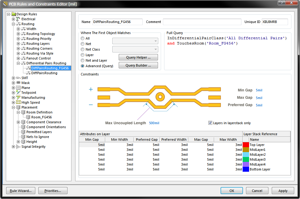
The Differential Pair Routing rule that defines the routing width-gap requirements in the Room_FG456. The room itself is defined by the Room Definition rule shown below, and used as the scope in other design rules by referencing its Name.
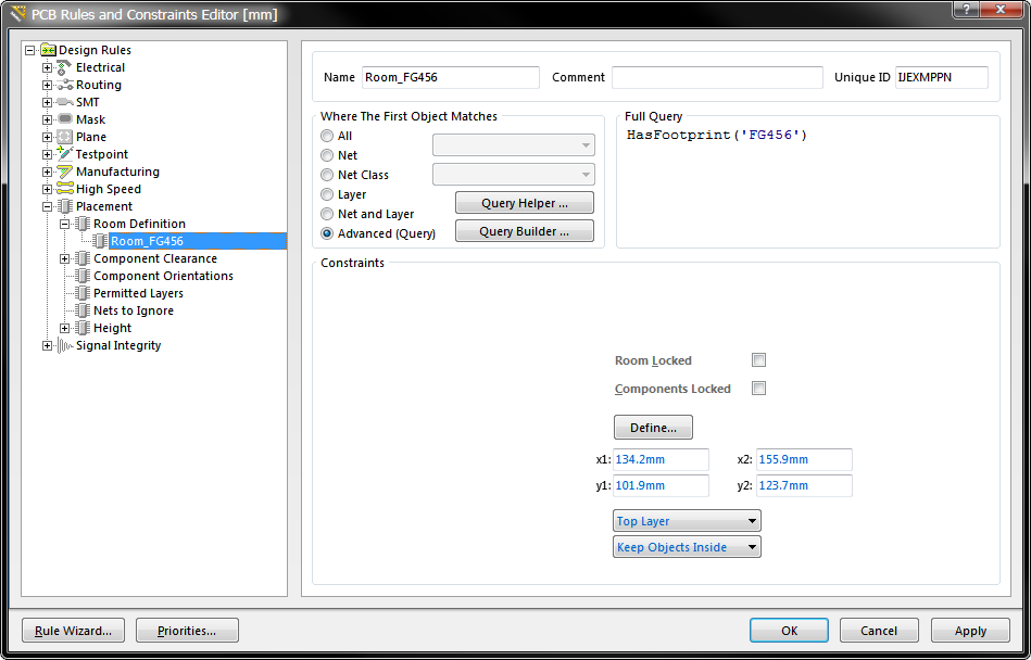
The Room Definition rule that defines an area under the BGA component. This room, named Room_FG456, can then be used to scope other design rules, such as the Differential Pair Routing rule.
Controlling the Placement Behavior on Width Change
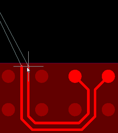
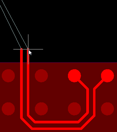
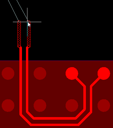
If you are routing and switching from a narrower width-gap rule to a wider width-gap rule, the cursor must be positioned between the centerlines of the new segments for them to appear, as shown in the animation below. This is done to ensure the placement behavior is predicable and controllable.
Position the cursor between the centerlines for the wider segments to appear.
Support for the Routing Layers Rule
The Routing Layers design rule allows you to specify which routing layers can be used. By scoping the rule to target specific nets, for example the differential pairs, you can then control which layers will be available during interactive routing of those differential pairs. The routing Width-Gap settings for each allowed layer are defined in the applicable Differential Pair Routing rule.
An example of the Routing Layers design rule, configured to control which layers differential pairs can be routed on.