Predefined Views for PCB in 3D
Contents
Displaying your board in 3D is the closest thing to having the real board in your hands, and all before sending it for a prototyping spin. However the beauty of having the physical board in your hands, is that you can naturally turn and rotate the board to view it from different perspectives. To accommodate similar ability in the design space, Altium Designer provides a set of predefined views when viewing your board in 3D. With a click of the mouse you can change view, enabling you to quickly appreciate the fruit of your design labor from various popular viewpoints.
Access
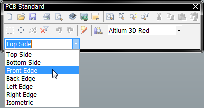
With the board being viewed in 3D mode, the predefined views are available from a drop-down field on the PCB Standard toolbar.
Supported Views
The following predefined views are supported when viewing a board in 3D.
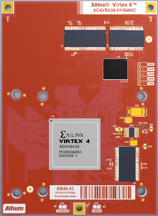
Top Side – viewing the board directly from above.
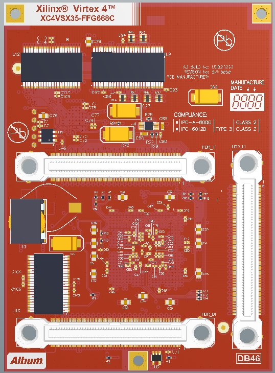
Bottom Side – viewing the board from the bottom (or its solder side).
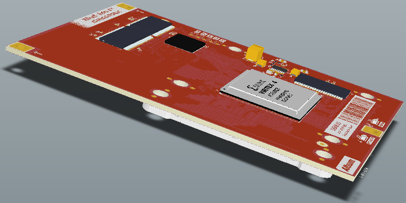
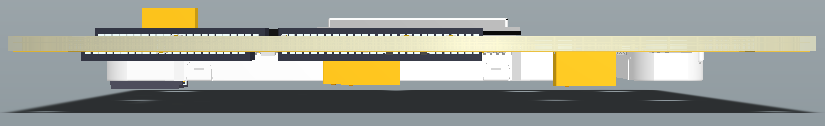
Front Edge – viewing the board from its front edge (or along the positive Y-axis).
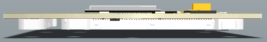
Back Edge – viewing the board from its back edge (or along the negative Y-axis).
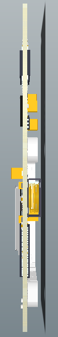
Left Edge – viewing the board from the left side (or along the positive X-axis).
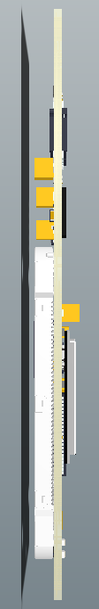
Right Edge – viewing the board from the right side (or along the negative X-axis).
Isometric – viewing the board in isometric projection.