PCB 3D Video
Contents
If a picture can 'tell a thousand words', it stands to reason that a series of pictures could convey far more information – a sequence of images used to visually educate the viewer about a topic. Extend this to a video, whereby static pictures are replaced with a smooth, dynamic flow, and the information presented becomes a concentrated burst of pin-pointed information to get you quickly up-to-speed with a particular subject matter.
In Altium Designer, the ability to take a snapshot of your PCB as a 3D printout provides a quick and easy way to share the look of the finished product with others, prior to physical production of the board. However, there's always something lacking when it comes to a single 3D print. You inevitably want to tilt the board, rotate it, or flip it between component and solder sides – all of which is not possible. Well, that's not entirely true. You could go back and rotate or flip the board in 3D view and output another print in each case, but at the end of the day, they are all still 'static' prints.
To offer more engaging, more useful documentation of your board, Altium Designer provides the ability to generate PCB 3D Video documentation. Donning your Director's hat, the content of a PCB 3D Video – or 3D movie if you prefer – is simply a sequential set of snapshots of your board (in 3D), referred to as Key Frames. For each subsequent key frame in the sequence, you can adjust zoom-level, pan and rotation directly in the workspace – all relative to the settings for the previous key frame.
In terms of output, a frame sequence is exported in a chosen video format, using the Multimedia Publisher – a configurable output medium, defined as part of an Output Job file. The result is a sequence of frames that smoothly interpolates the key frame sequence.
So, whether you're creating an assembly instruction manual, a demonstration of moving parts, or just wanting to provide a snazzy flyover of the angles that make your product look best, PCB 3D Video provides an attractive and informative addition to your product documentation arsenal.
Making a PCB 3D Video
Panel reference: PCB 3D Movie Editor
PCB 3D Videos are created, configured and managed, from within the PCB 3D Movie Editor panel. Access this panel by clicking on the PCB panel-access button – at the bottom-right of the main design window – and choosing the PCB 3D Movie Editor entry from the subsequent menu that appears.

The PCB 3D Movie Editor panel - command central for creating and configuring your 3D movies
The panel is essentially divided into three regions. The upper region provides an area for managing your 3D movies – adding and deleting movies. The central region of the panel contains the key frame sequence definition. From this region, you can add new key frames, and update key frames based on changes made to the display of the 3D board in the workspace. The lower region of the panel contains controls for playing back a selected movie directly in the PCB workspace.
3-Dimensional Filming Only
Although the PCB 3D Movie Editor panel can be accessed irrespective of the current viewing mode set in the PCB Editor, its controls – and therefore your movie-making abilities – are only enabled once the board is being viewed in 3D. A warning is provided in the dialog when viewing the board in 2D to alert you to this fact.
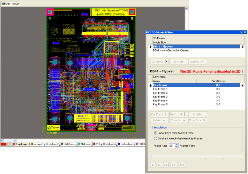
If you are not viewing the board in 3D, the PCB 3D Movie Editor panel will be disabled\!
Video Playback
Once you have defined the content of your PCB 3D Video, in terms of its key frame sequence, you can preview the resulting video directly within the PCB Editor. To do this, simply select a movie title in the upper region of the PCB 3D Movie Editor panel, and click the ![]() button – part of the playback controls – in the lower region.
button – part of the playback controls – in the lower region.
Altium Designer becomes your very own movie theater - just select a movie, press Play, then sit back and enjoy the fruits of your labor\!
Playback Controls
Pressing 'play' gets you going fast, but we all like to have full control when watching a movie. The ability to skip back and forth through scenes and, of course, the ability to pause the movie when we see something we really like! 3D movie playback is no exception, and controls are provided in the panel to give a richer viewing experience. The following is a summary of the full set of controls available:
![]() – play back the movie from the current marker position on the associated timeline.
– play back the movie from the current marker position on the associated timeline.
![]() – pause playback of the movie.
– pause playback of the movie.
![]() – rewind the movie back to its start. This is the first key frame, denoted by time zero on the associated timeline. This control is only available while the movie is not playing.
– rewind the movie back to its start. This is the first key frame, denoted by time zero on the associated timeline. This control is only available while the movie is not playing.
![]() – jump to the start of the next key frame in the sequence. This control is only available while the movie is not playing.
– jump to the start of the next key frame in the sequence. This control is only available while the movie is not playing.
![]() – jump to the start of the previous key frame in the sequence. This control is only available while the movie is not playing.
– jump to the start of the previous key frame in the sequence. This control is only available while the movie is not playing.
A timeline reflects where, in the overall movie, playback has currently reached. While the movie is not playing, you can manually drag the timeline's marker to any point – a pop-up reveals the exact time.
Dragging the marker along the timeline effectively performs manual playback.
Interpolation Settings
Playback of a 3D movie within the PCB Editor is made possible using interpolation between the defined key frames, and additional smoothing. There are two types of interpolation that can be employed, with options to switch between the two available just above the playback controls.
Specify the style of interpolation used to create a seamless flow between one key
frame and the next, and also the rate at which frames are played back.
- Linear Key Frame to Key Frame – uses spherical linear interpolation between key frames, and additional smoothing that results in a slow-down at the end of each frame.
- Constant Velocity between Key Frames – uses quadratic-spline interpolation between key frames and also divides the range in rotations to be smaller then 90 degrees. The result is a more seamless transition between key frames, with a constant speed between frames rather than any noticeable slow-down.
Playback within the PCB Editor is at a default frame rate of 25 frames per second. The total number of frames used in the video will depend on the Duration set for each key frame. Use the Frame Rate field to increase or decrease this rate as required. The frame rate can be any value between 1 and 50.
When generating actual video output using the Multimedia Publisher, the frame rate is set to 25 frames per second by default.
Generating PCB 3D Video Output
Related article: Video Output Container
You've defined all the key frames you require in your sequence, and a quick preview has shown all is good-to-go. Now you can go ahead and generate some output! PCB 3D Video output is configured as part of an Output Job file, and is generated using the Multimedia output medium – also referred to as the Multimedia Publisher.
Adding and Configuring a Multimedia Output Medium
Add a Multimedia output medium to your Output Job file, by clicking on the [Add New Output Medium] button (in the Output Media pane) and selecting Multimedia from the list of media available. Configuration of the medium is performed from within the Multimedia Settings dialog – accessed by right-clicking on the medium and choosing Multimedia Setup from the context menu.
Use the Multimedia output medium to publish your PCB 3D Video(s).
By default, the publisher is set to generate a single video file that will be stored in the project's sub-folder Project Outputs for ProjectName. The video file will be named using the Output Job file name. Change output settings as required.
Adding and Configuring a PCB 3D Video Output Generator
Add an output generator for each 3D movie you want to publish. In the Documentation Outputs section of the Output Job file, click on the [Add New Documentation Output] button and choose the PCB 3D Video entry, along with the source PCB document to which the 3D movie is associated.
Add a PCB 3D Video output generator for each 3D movie that you want to publish.
As part of its configuration, the Multimedia Publisher can generate a single movie from all enabled PCB 3D Video output generators associated to it, or you can specify that a separate file is generated for each output. If you opt for the latter, each file will be named using the entry for that output generator's name in the Output Job file. In this case, you may want to name a generator using a more meaningful name – perhaps using the title you defined for it in the PCB 3D Movie Editor panel.
Use the Name field for a PCB 3D Video output generator to obtain a more meaningful filename
when publishing multiple videos as separate files, using the same Multimedia output medium.
Configuration of a PCB 3D Video output generator is performed from within the PCB 3D Video dialog – accessed by double-clicking on the output generator, or right-clicking on it and choosing Configure from the context menu. Use the dialog to primarily select which 3D movie to use, from a list of those currently defined for the PCB document specified in the Data Source field.
Choose the 3D movie you want to use as the
source for the generated video.
Two additional controls are provided that can be used to further define the display of your PCB 3D Video. The ![]() button allows you to toggle the display of a shadow effect for the board.
button allows you to toggle the display of a shadow effect for the board.
Enhance the display of your board by applying a 3D shadow effect.
To get the best out of your leading board in its starring role, you might think about changing the boards' appearance – or wardrobe as they say in Hollywood! Use the ![]() button to access an instance of the View Configurations dialog. From here, you can adjust the look and feel of your board, and change any settings for 3D Bodies and STEP models as required – ensuring your board looks its best for that all important video close-up!
button to access an instance of the View Configurations dialog. From here, you can adjust the look and feel of your board, and change any settings for 3D Bodies and STEP models as required – ensuring your board looks its best for that all important video close-up!
Use the View Configurations dialog to adjust the board's appearance as required.
Publishing
Once you have added and configured the Multimedia output medium and the PCB 3D Video output generator(s) as required, you are just steps away from publication. With the Multimedia output medium selected, click on the Enable field for each PCB 3D Video output generator to be included in the publishing process. An enabled generator will have a green line connecting it to the output medium.
Enable each PCB 3D Video output generator whose specified 3D movie you want to have published by the Multimedia output medium.
Then simply click the Multimedia button above the Output Media pane (shortcut, F9). Publication will proceed and the video(s) will be generated and stored in the specified folder. If you have chosen to open the video after export, it will open and start playing – provided you have software installed on your computer with which to do so.
Generate video and watch the star of the show - your board\!
When generating multiple videos as separate files (generated by the same Multimedia output medium), the PCB 3D Video output generator enabled as the first output (carries number 1 in its Enabled field) will be the one opened and played after export (where enabled to do so).