Outline Vertices Editor for Polygonal Pours and Regions
Contents
Offering additional versatility when defining polygonal-based objects in a design – Polygon Pours and Regions (solid, polygon pour cutout, board cutout) – Altium Designer provides support for table-based editing of outline vertices. Made possible through a dedicated Outline Vertices tab in the Polygon Pour and Region dialogs, you can modify the locations of existing vertices, add new vertices, or remove them as required. Arc connections between vertex points can be defined, and support is also provided for exporting vertex information to, and importing from, a CSV-formatted file. You can even adjust the position of a polygonal object by globally applying delta-x/delta-y values to all vertex points.
Access
Non-graphical editing of the vertex points for a placed polygon pour is performed in the Outline Vertices tab of the Polygon Pour dialog. Double-click a polygon pour to quickly access this dialog.
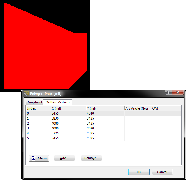
Make changes to a polygon pour's shape through table-based editing of its outline vertices.
Likewise, editing of the vertex points for a placed region object is performed in the Outline Vertices tab of the Region dialog. Double-click a region object (solid/copper region, polygon pour cutout region, or board cutout region) to quickly access this dialog.
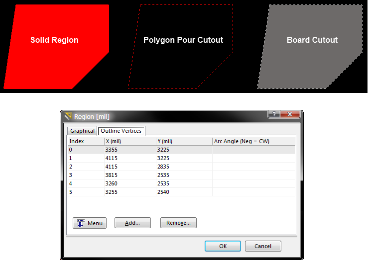
Make changes to a region's shape through table-based editing of its outline vertices.
Making Changes to Vertices
Use the various controls available in the Outline Vertices tab to make the necessary changes to the polygonal shape of the polygon pour or region as required. For a region, changes made will be applied after clicking OK. For a polygon pour, changes will be effected once the polygon is rebuilt. Note that full controls are available from both the right-click menu for the tab, as well as from the menu associated to the Menu button.
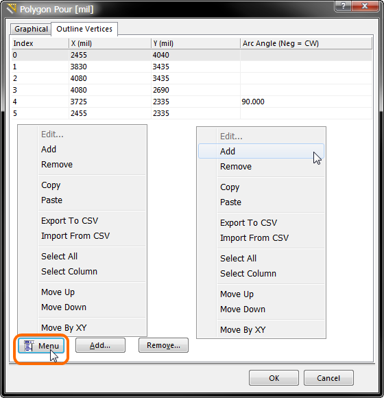
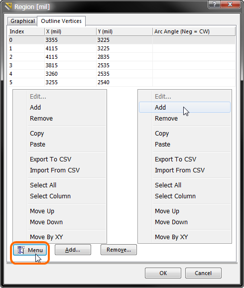
Access the full range of editing controls through the Menu button or right-click menu.
The following sections take a look at working with this tab to effect the changes required to the outline of a polygonal object. Although a polygon pour has been used as the test subject, the information applies equally to a region object.
Adding a Vertex Point
To add a new vertex to the polygon's outline, select the existing vertex in the list – before the desired insertion point – then click the Add button (or choose Add from a menu). The new vertex will be added to the list, initially with the same X,Y coordinates as the selected vertex preceding it. Change the coordinates as required.
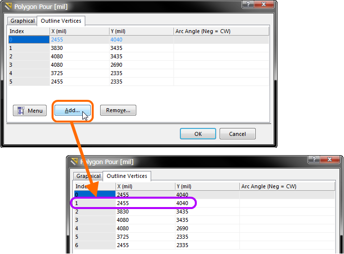
Example addition of a new vertex point.
Editing a Vertex Point
Editing an existing vertex is simplicity itself. Click once to focus the X or Y coordinate. Then click again to enter in-place editing mode. Type the new coordinate as required, then press Enter or click away from the field.

Example single-cell editing.
Multi-cell selection and editing is also supported (within the same column). To edit multiple selected cells, use the Edit command from a menu. The focused cell in the selection (distinguished by a dotted cell outline) will enter in-place editing mode. Type the required value and press Enter (or click away). All cells in the selection will be updated to have that same value.
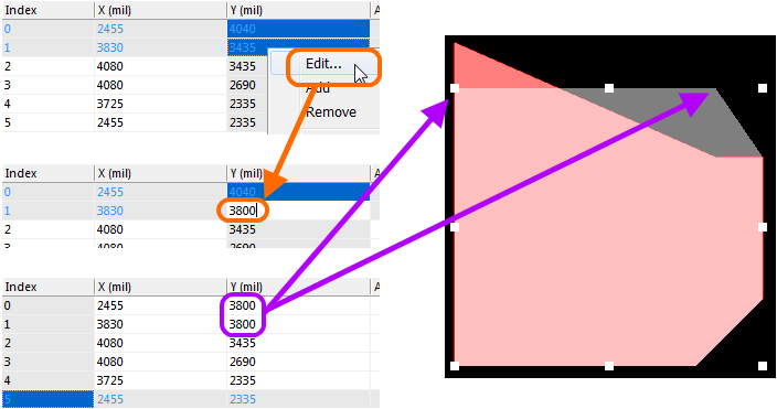
Example multi-cell editing to change the Y coordinate of two vertex points.
Defining an Arc
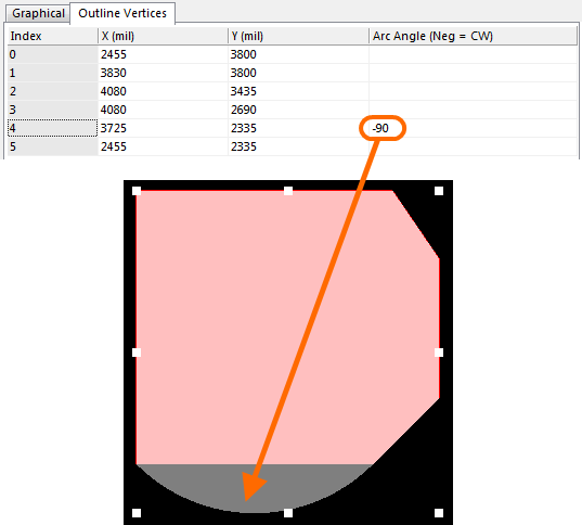
Straight line edges are used to connect one vertex point to the next. If you would rather have an arc connection, simply enter a value for the required Arc Angle. Entry is made in the field associated to the source vertex point, with the arc being from this vertex to the subsequent vertex below in the list.

Example 90 degree arc from vertex 4 to vertex 5.
Entry of a positive value for the Arc Angle will result in an arc drawn counter-clockwise. To draw a clockwise arc, enter a negative value.
Example of 90 degree arc drawn clockwise, by defining the Arc Angle to be negative.
Removing a Vertex Point
To remove a single vertex point, simply select its entry in the list, then click the Remove button (or choose Remove from a menu).
To remove multiple vertices, simply select them as required using standard multi-select features (Ctrl+click, Shift+click, drag-select). Then click Remove.
Global Move by XY
The entire outline for the polygon can be moved in the workspace, by specifying an incremental distance to be added globally to all vertex X and or Y coordinates.

Incrementing all vertex coordinates by specific delta values. Use this feature to precisely locate the polygon in the workspace.
Export/Import
The Outline Vertices tab provides controls for exporting and importing defined vertices. Vertex information is stored in a CSV-formatted file (*.csv).
To export the defined vertices, use the Export To CSV command from a menu. The full list will be exported, there is no need to select anything prior to launching this command. Use the subsequent Export Outline Vertices dialog to determine where, and under what name, the file is to be saved.
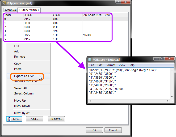
Exported vertex information for an example polygon.
The vertices can be modified as required externally, for example in your favorite spreadsheet editor. Once modified, you can import the new vertex information using the Import From CSV command from a menu. Use the Import Outline Vertices dialog to browse to, and open, the required CSV file. The contents of the file will completely overwrite existing vertices in the Outline Vertices tab.
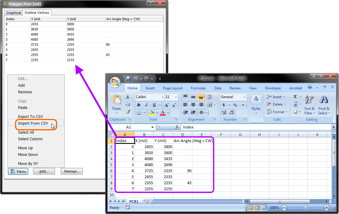
Make changes to vertices in an external spreadsheet editor, then import the modified csv file back into the Outline Vertices tab.