Modifying Existing Routing
Contents
Routing is probably the most iterative process you perform designing a board, constantly defining and re-defining connection paths as the board layout evolves. This iterative nature requires routing modification tools that compliment the interactive routing tools. Altium Designer includes features that allow you to modify existing routing with either your re-router's hat on - let me redefine that routing path, or your drafter's hat on - let me move that set of tracks over to free another routing channel.
The re-router is supported by a feature called Loop Removal. The drafter is supported by sophisticated dragging capabilities, which are actually useful for both modifying existing routing, and creating new routing - but more on that later.
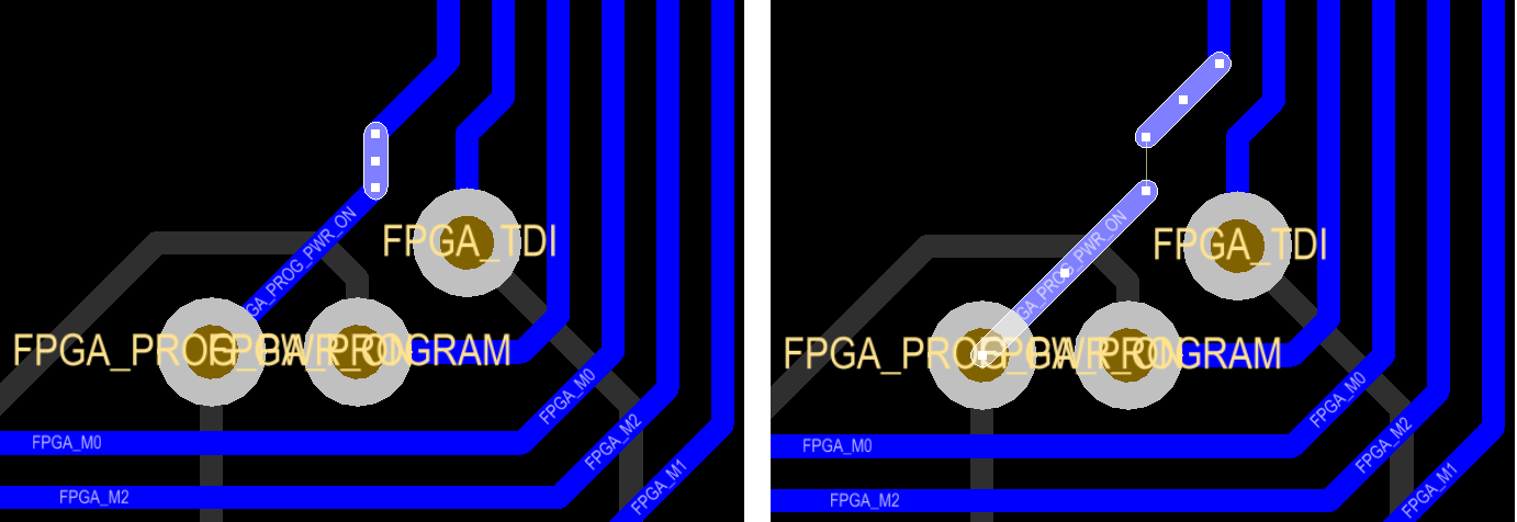
Rerouting an Existing Route - Loop Removal
As you route there will be many instances where you need to change some of the existing routing. Rather than attempting to change the existing routing using a drafting type approach of clicking and dragging track segments, you re-route. To do this you select one of the Interactive Routing commands from the Place menu, click on the existing routing to start and then route the new path, coming back to meet the existing routing. This will create a loop with the old path and the new path, no need to worry though, as soon as you press ESC to terminate the route the redundant segments are automatically removed, including any redundant vias. This feature is known as Loop Removal.

Redefine the route path by simply re-routing along the new path, the old routing loop is automatically removed.
Protecting an Existing Route
There are times when this loop removal behavior works against you though, for example, when you are routing a power net. You can disable Loop Removal selectively for any net, double click on the net name in the PCB panel and clear the Remove Loops option in the Edit Net dialog.
To protect an existing route from being pushed/shoved as you route other nets, you need to lock those track segments. The easiest way to do that is to select the track segments and enable their locked attribute. To select all connected copper press the Ctrl+H shortcut and click on a track segment (once done press Esc to drop out of select mode), then press F11 to open the Inspector panel so they can be locked.
The Inspector panel defaults to load all selected objects, this could include tracks, pads, vias and other objects being used to create the routing. To restrict the locked setting to specific objects, click the Include all types of objects link at the top of the panel and enable the required object kinds, as shown in the image below. Once the required objects have been enabled, click the Locked checkbox to lock just those objects.
Once the routing has been selected, choose the types of objects to be locked in the Inspector, then Lock them.
Track Dragging with Angle Preservation
Re-routing is not always the best approach to modifying routing, for example, situations where you want to move a track segment slightly, keeping the neat 45° and 90° corners at either end. Altium Designer supports this, through multi-track dragging with angle preservation. Dragging behavior is controlled by the Preserve Angle When Dragging option in the PCB Editor - Interactive Routing page of the Preferences dialog.
To drag, click once on the segment to select it - the cursor will change to a quad-arrow - then click and drag to slide it to a new location. You will notice that the angles to adjacent track segments are preserved, maintaining the routing style.
All the selected segments are dragged at the same time.
By selecting first, you indicate that you want segments connected at either end to remain connected. Alternatively, use the CTRL + Left click & Drag to drag an individual segment without having to select first. Multiple selected track segments can also be dragged, as long as they share the same orientation and are not part of the same connected copper.
To easily select multiple track segments for dragging, press S to pop up the Select sub-menu.
Like the interactive routing modes, you can use the SHIFT + R shortcuts to cycle through options that control how obstacles should be handled during dragging (Ignore Obstacle, Avoid Obstacle or Avoid Obstacle (snap grid)). If one of the Avoid Obstacle modes is enabled, the rules will be obeyed during dragging, preventing you from dragging a segment into violation. It also supports pad/via hopping, allowing you to drag a walk-around from one side of a pad or via to the other side.
Dragging on a track end will add a segment to preserve the routing quality, hold the ALT key before dragging to move the end of the segment. Dragging on the center handle will break the track, adding segments to maintain the orthogonal/diagonal connections.
Use the center track handle to break an existing segment.
Incremental Unroute of Existing Route
While in interactive routing mode, should you wish to rip-up and essentially unwind the track you are currently placing, you can do so using the Backspace key. But what about after the track has been laid? Wouldn't it be neat if you could do something similar post-route? Sure, there are a range of unroute commands, but how about something that is there at your fingertips, enabling you to incrementally unroute existing routing?
Altium Designer's PCB Editor includes two shortcut-based features to support incrementally unrouting existing routing.
Ctrl + Delete
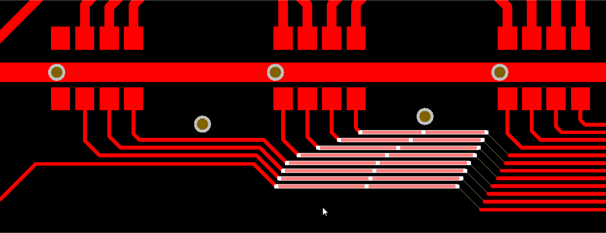
Use the Ctrl + Delete shortcut to delete one or more selected routing objects. These can be component-free tracks, arcs, vias, and pads. All route objects connected to those deleted will be automatically selected, ready for subsequent deletion. The view will change accordingly, so that the selected objects for potential deletion are always in view.
The image below illustrates use of the command by deleting a track segment in the middle of a route. Notice that the contiguous routed track segments either side become selected. Successive use of the feature would incrementally unwind the routed path in both directions.
Example deletion of a selected mid-route track segment. Connected segments either side are selected ready for further deletion.
The animated image below shows use of the feature to unwind multiple routed paths simultaneously.
Using the Ctrl + Delete feature to unwind multiple routed paths.
Backspace
Use the Backspace shortcut to delete a single, selected end-of-route object. Again, this can be a component-free track, arc, via, or pad. The singular route object connected to the deleted object will be automatically selected, ready for subsequent deletion. The view will change accordingly, so that the selected object for potential deletion is always in view. Successive use of the feature would incrementally unwind the routed path, in much the same way as using the Backspace shortcut while routing.
Incrementally unrouting a single route using the Backspace key.
See Also
Getting ready to route
Interactively Routing a Net
Differential Pair Routing
Tuning Route Lengths
Fanout and Escape Routes