Live Drill Table
Contents
A standard element required for manufacture of a Printed Circuit Board is a drill drawing table, also known as a drill table or a drill drawing legend. The drill table lists the size and number of holes for each drill used on the board. Each drill size can be represented by a symbol, a letter or the actual hole size. When a drill drawing is generated for the board, each actual drill site is marked by a symbol, as shown in the image below. The Live Drill Drawing table updates in real time - as hole-containing objects such as pads and vias are placed on and removed from the PCB design, the table updates.
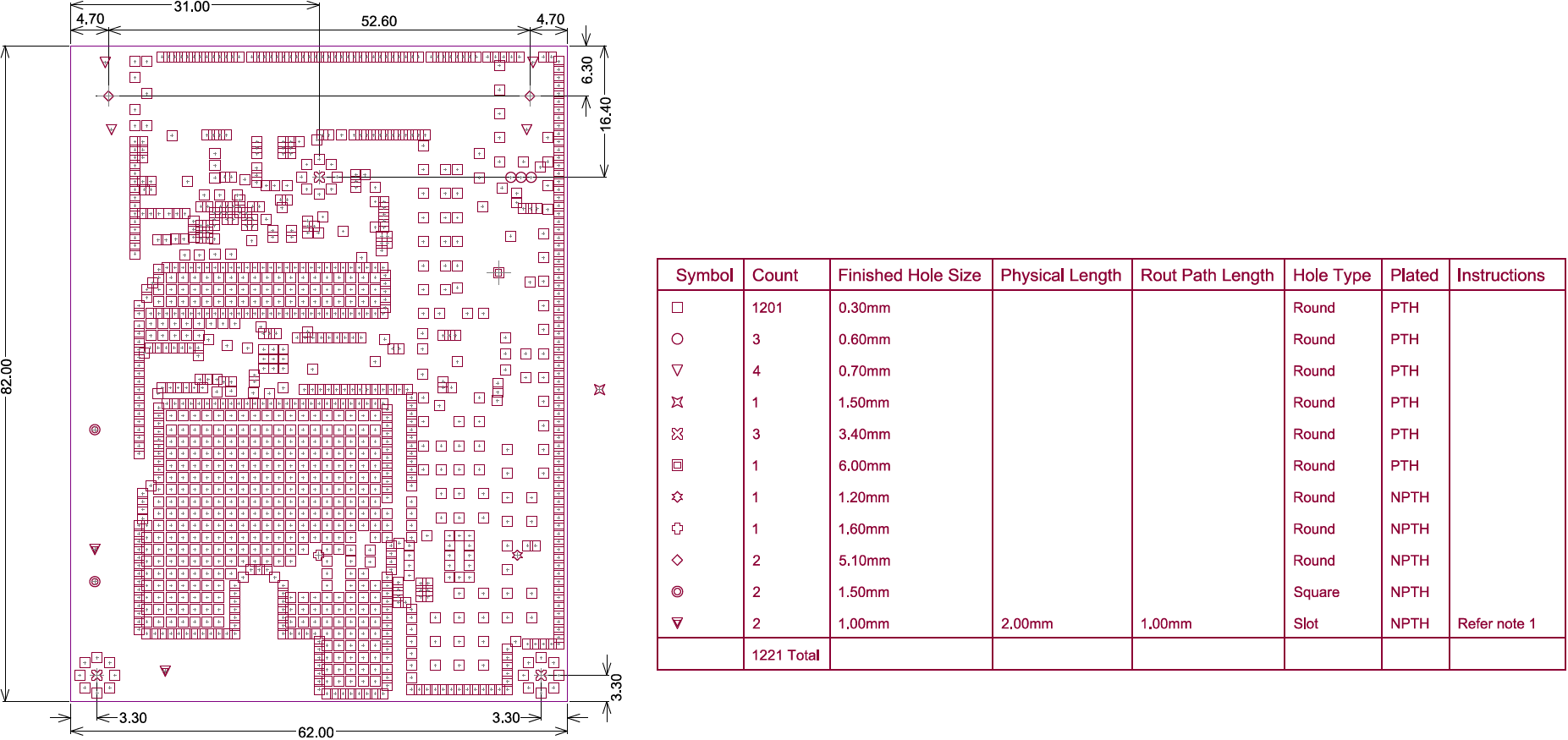
An example of a Live Drill Table, and the results produced on the Drill Drawing Layer when the output is generated.
Placing and Editing a Live Drill Table
Dialog page: Drill Table
To place a Drill Table, select Place » Drill Table from the PCB Editor menus. A Drill Table object will appear attached to the cursor, position it in the workspace and click to place it. The list of holes displayed in the Drill Table is automatically generated, as soon as a hole-containing object, such as a pad or via, is added or deleted from the PCB the list is updated.
Double-click anywhere on the Drill Table to open the Drill Table dialog and edit the presentation of the table.
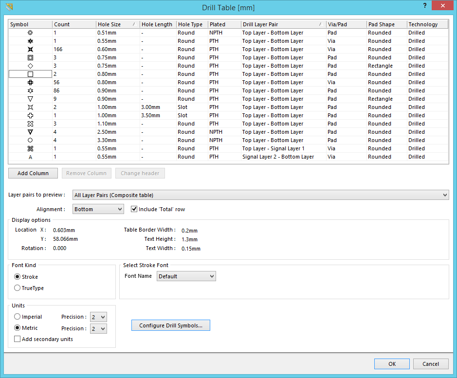
Configure the presentation of the Drill Table in the Drill Table dialog. Use the buttons below the grid to modify the columns, or right-click in the grid area for more column editing options.
Drill Table Settings
As shown in the image above, the upper region of the Drill Table displays a grid of the various drill sizes used in the design, which defaults to sort by drill size. All holes are included in the Table, including round, slotted and square holes. Slotted holes include the Physical path length, which is the tool center travel distance; as well as the total Rout path length, which is the end-to-end distance of the slot.
Sort Order
To sort the Drill Table, click the required column heading. A small triangle will appear, indicating the current sort direction - click a second time to reverse the sort direction. Multi-level sorting is supported, hold the Shift key as you click to sub-sort by a second (or third) column. In the image below the table has been sorted by:
- Plated (to separate plated from non-plated), then
- Hole Type (to order holes to Round then Slot then Square), then
- Finished Hole Size (to order by size).

Sort the drill table by clicking the column headings, hold shift and click to sub-sort by other columns.
Customizing the Table
The Drill Table can be customized, including:
- Changing the column order - click and drag on a column header to change the order of columns.
- Change a column header - select the column then click the Change Header button, or right-click in the column and select Change Column Header from the menu.
- Hide a column - select the column then click the Remove Column button, or right-click and select Remove Column from the menu.
- Show a column - click the Add Column button then select the required column, or right-click and select the relevant Add Column menu entry.
- Add a Custom column - click the Add Column button then select Custom column, or right-click and select the Add Column » Custom Column menu entry. Both the header and the values are user-defined in a Custom column.
- Text Alignment - right-click and select the required alignment option from the Text Alignment sub-menu. Note that the alignment option is used for the placed Drill Table, not in the Drill Table dialog.
- Set Column Width - right-click and select the Autosize or Manual option from the Set Column Width sub-menu. Note that the manual setting is applied to all columns.
Layer Pairs to Preview
The Live Drill Table supports multi-layer boards that use layer-pair drilling. To support the designer in using the Live Drill Table during the design process the table includes the Layer pairs to preview option, set this to restrict the table to only show the drill holes for just the selected layer-pair. Note that the Layer pairs to preview option is not used to control which layer-pair drilling is included in the Table during output generation, that is defined by the Drill Layers setting in the Layer Properties dialog in the output setup. That means that a single table can be placed on the design, the table will only include the appropriate layer-pair data during output generation of a drill drawing of that layer-pair.
Configuring the Drill Symbols
Dialog page: Drill Symbols
Drill symbols are assigned to hole sizes in the Drill Symbols dialog, click the Configure Drill Symbols button at the bottom of the Drill Table dialog to open it. The initial assignment of a symbols to hole sizes is performed automatically, which can then be changed if required.
Each symbol is mapped to a hole size based on the currently enabled grouping options, click the Grouping button to enable the grouping options you want used as criteria for determining uniqueness of hole size. Hole objects must share the same values in all visible grouping columns to be considered the same, if they are they will be assigned to use the same symbol. For example, pads and vias with the same size hole will share a symbol, but if the Via/Pad option is enabled in the Grouping list (so that the Via/Pad column is displayed), then they will be listed separately and be assigned different symbols.
Interactively Resizing a Drill Table
The Drill Table is automatically sized based on the specified Text Height setting, as well as the number of different hole sizes (rows) and the number of defined columns. To interactively resize the table, click once to select it, then click and hold on a corner vertex. The Confirm dialog will appear, reporting that the table is locked, click Yes to continue and resize the table.
Interactively Switching the Layer Pair to Preview
When the board includes layer-pairs, the displayed layer-pair is controlled by the Layer pair to preview option in the Drill Table dialog.
This chosen layer-pair can also be switched using the:
- PCB Editor right-click menu, simply right-click on the Drill Table and select the required layer-pair in the Drill Table sub-menu, as shown in the image below.
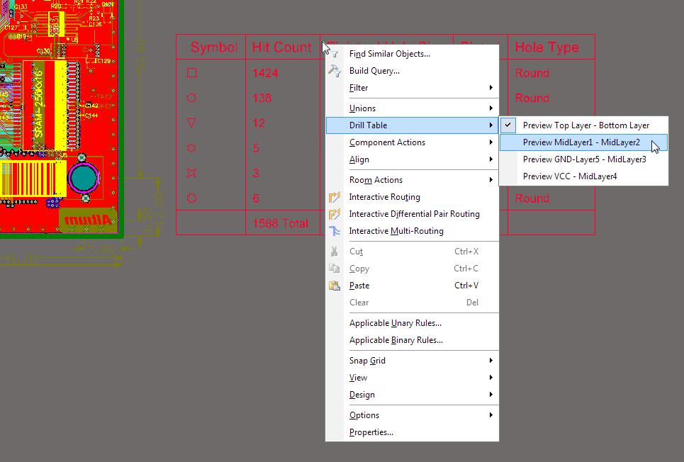
Right-click on the Drill Table to switch it to display another layer-pair.
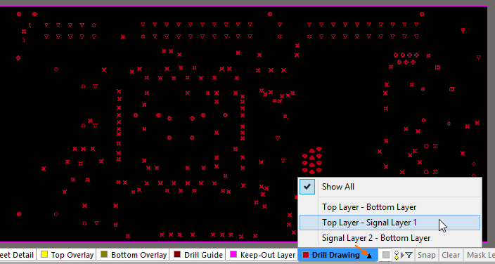
- Layer-pair selection menu accessed via the Layer Tab at the bottom of the workspace, as shown in the image below.
Configuring the Default Drill Table
All of the Drill Table presentation settings, such as the column order, font size and display units, can be pre-configured by setting the defaults. This is done in the PCB Editor - Defaults page of the Preferences dialog. Double-click on the Drill Table entry in the Primitive Type list to open the Drill Table dialog.
Edit the settings as required. To edit a column setting, right-click on the column header to display the context menu. Note the state of the Permanent checkbox in the PCB Editor - Defaults page, if this option is off then you can also change the defaults of any object during object placement by pressing the Tab key while the object is floating on the cursor, before it is placed.