IDF and STEP Output via an OutJob
The Intermediate Data Format (IDF) and STEP are formats that can be used for exchanging printed circuit assembly information between ECAD and MCAD systems.
Altium Designer supports the export of your PCB in both IDF and STEP formats, as part of output generation through an Output Job Configuration file. To make use of this feature, ensure you have the Output - IDF and /or Output - STEP plugins installed as part of your installation. This can be found on the Output Generators page, when browsing available plugins in the Plugins view (DXP » Plugins and Updates).
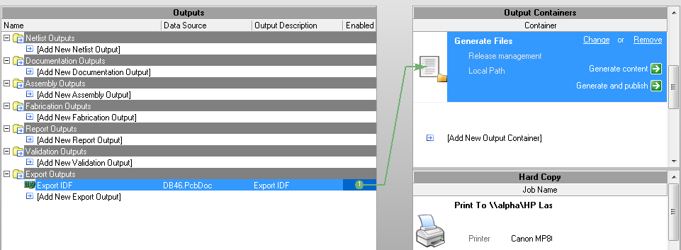
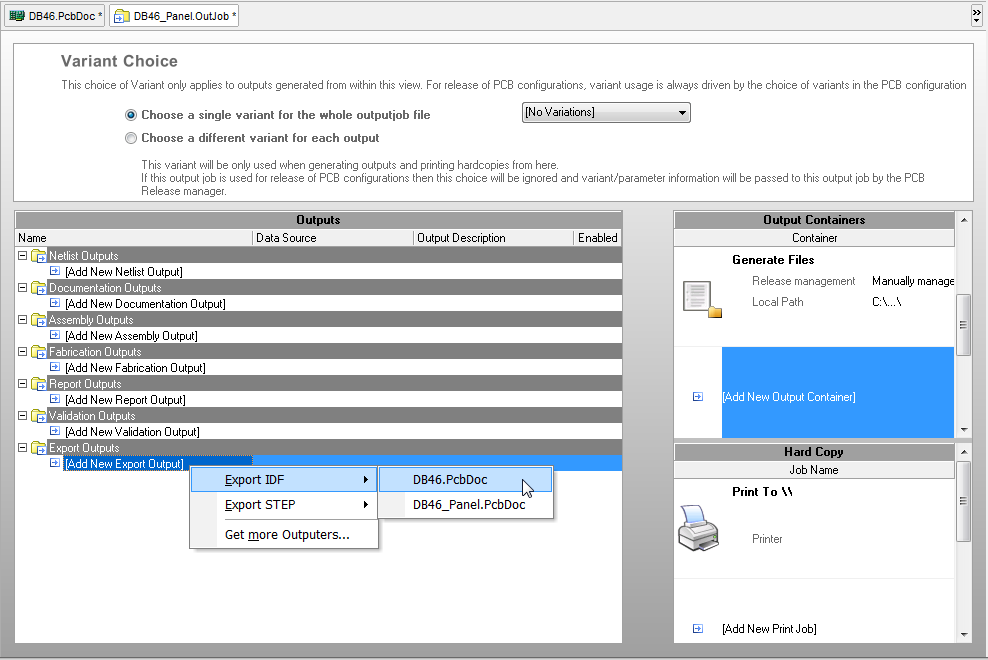
Add an output generator of the required type from the Export Outputs section of the OutJob file.
Configuring an IDF Output
Double-click on the entry for the output generator (by default named Export IDF) to access the File Export IDF dialog. Use this dialog to configure export options as required.
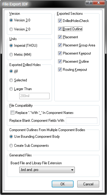
Altium Designer supports export to IDF v2 or v3 format. These formats are much the same in terms of structure and content. They include basic information about the shape of the board, the position and size of plated and non-plated holes, and the position and basic shape of components. The v3 format supports additional keepout and outline types.
Exporting to either of these versions will generate two files on disk – one containing information about the physical size and shape of the PCB and positions of components, and the other containing information about each component including name, size and shape. These are typically referred to as the Board and Library files respectively.
If component bodies are used the information in the library file is a lot more usable. The ideal solution is to have a 3D representation of the component in your MCAD package, which is placed from the library information.
Different CAD packages use different file extensions for these board and library files. Use the Generated Files region to specify from the following extension pairs:
.brdand.pro.brdand.lib.emnand.emp.bdfand.ldf.idband.idl
Since the output being generated is files on disk, the output can only be linked to File Structure type Output Container.