Enhanced PCB Filtering
Contents
The PCB Filter and PCBLIB Filter panels have been given a complete overhaul in Altium Designer 14.3, streamlining your ability to locate objects in a design or library, and to select those objects ready for editing. The panels now provide a quick means of building simple filters based on object type selection, as well as the more traditional use of free-hand construction of expressions, for more advanced filtering. The result is that you can pinpoint the required objects with the same great accuracy and efficiency you've come to rely on through each panel, but doing so with a fresh, more intuitive interface.
Same Name, Different Face
They're still the PCB Filter and PCBLIB Filter panels. And they're still accessed in the usual ways. But the moment you do access either panel, you'll observe a sleak new interface – especially if you are a seasoned Altium Designer user and know the panels of old.
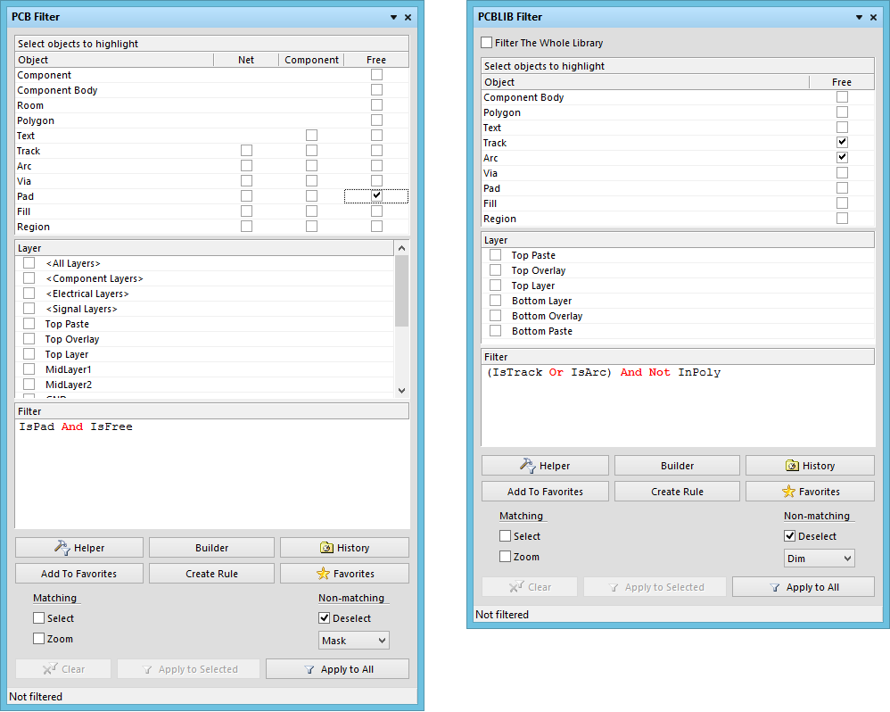
The new-look PCB Filter and PCBLIB Filter panels.
The following sections take a look at the interface and use from the perspective of the PCB Filter panel. The interface and operation of the PCBLIB Filter is essentially the same. Where specific differences exist, these are highlighted where applicable and appropriate.
Building Simple Filter Expressions
The main region of the panel provides controls for quickly building simple filter expressions targeting any combination of objects. Object types are arranged in an 'object matrix', categorized in accordance with being net objects (Net), component objects (Comp), or free objects (Free). The following core object list is replicated across these three groups:
- Track
- Arc
- Via
- Pad
- Fill
- Region
The Text object is available as part of the Comp and Free groupings, but, as this object type is not net-aware, it is not part of the Net grouping. In addition, the Free grouping also includes: Component, ComponentBody, Room, and Polygon.
To use an object in the construction of a filter expression - thereby filtering by that object - simply enable the relevant check box associated with that object, within the object matrix. Commands available on the right-click context menu for the region enable you to quickly check or uncheck all entries in the matrix, or toggle the state of all checkboxes in the matrix, respectively.
Use the Layer region of the panel to restrict the filter to a particular layer, or layers, or a specific class of layers. The entries listed reflect:
- The defined layer classes for the board, the default of which are:
- <All Layers>
- <Component Layers>
- <Electrical Layers>
- <Signal Layers>
- The defined layers in the layer stack (as presented in the Layer Stack Manager dialog).
- The top and bottom paste mask layers.
As you make your filtering selections, the resulting query expression is built dynamically, and presented in the Filter region of the panel. Once the filter query expression has been defined as required, you then need to apply it as a separate action. Do this using the Apply button at the bottom of the panel. Alternatively, if you require application to only those objects that are currently selected in the workspace, use the Apply to Selected button instead.
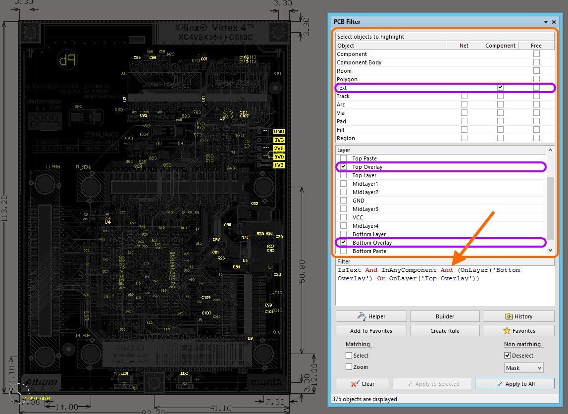
Example of quick, simple filtering in action, with the resulting query expression - used by the filter engine - built only from objects and layer(s) specified.
Building Advanced Filter Expressions
The Filter region of the panel allows you to build filters of any complexity through the creation of logical query expressions.
While the upper regions allow a simple filter expression to be quickly built, more advanced expressions can be constructed. Advanced query expressions can be defined in the following ways:
- Typing a query directly into the main expression window. As you type, a prompt list of possible keywords will appear as an aid.
- Using the Query Helper (click the Helper button). Once launched, the underlying Query Engine analyzes the document and lists all available objects along with generic keywords that can be used in queries.
- Using the Query Builder (click the Builder button). The Query Builder enables creation of a query for targeting specific objects in the design document, by simple construction of a string of ANDed and/or ORed conditions.
- Modifying the expression obtained through simple object/layer selection in the regions above.
Again, once you have defined your filter query expression, you then need to apply it by clicking the Apply button (or the Apply to Selected button for application of the filter to currently selected objects only).
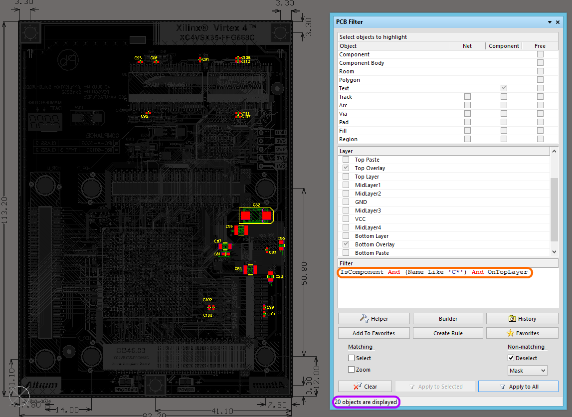
Example application of a more advanced filter, with the query expression entered directly into the Filter region of the panel. Again, the number of filtered objects is reflected at the bottom-left of the panel.
Filter Highlighting
Before application of the query in the panel, it is best to define how you wish the result of the filtering to appear visually in the design workspace. The lower region of the panel provides various options which collectively form the highlight controls for permanent filtering.
The Matching options allow you to control how all objects that fall under the scope, and match the specific query expression of the filter, will be visually displayed in the workspace:
- Select - when enabled, the filtered objects will be selected in the workspace.
- Zoom - when enabled, the filtered objects will be zoomed and centered (where possible) in the main design window.
Conversely, the Non-matching options allow control over the visual display - in the workspace - of all objects that do not fall under the scope and/or do not match the specific query expression of the filter:
- Deselect - when enabled (default), all objects not falling under the scope of the filter will be deselected in the workspace.
- Normal/Mask/Dim - this dropdown provides you with the following options for visibly contrasting filtered and unfiltered objects within the design editor window:
- Normal - filtered objects are highlighted, however, the appearance of unfiltered objects remains unchanged.
- Mask - filtered objects will appear visible in the design editor window, with all other objects being made monochrome. When this option is applied, unfiltered objects will be unavailable for selection or editing.
- Dim - filtered objects will appear visible in the design editor window, with all other objects retaining their colors, but being shaded.
Clearing the Current Filter
The currently applied filter can be cleared in a number of ways:
- Click the Clear button, at the bottom left of the panel.
- Click the Clear button, at the bottom-right of the main design window.
- Press the Shift+C shortcut keys.
- Clear the entry for the current expression and press Enter, or click the Apply button.
Favorites & History
Over time, a number of useful query expressions will be constructed in the course of laying out various boards. Typically, a designer will want to apply and re-apply the same queries, not only in the same design, but across different designs. To cater for this, the panel supports the notion of Favorite and Historical queries.
As a query is entered and applied from the panel, it will be added to a query 'history list'. In addition, that query can be added to a query 'favorites list', by clicking the Add To Favorites button, below the filter expression window. Use the History and Favorites buttons in the panel to access the corresponding tabs of the same name within the Expression Manager dialog, to see these lists.
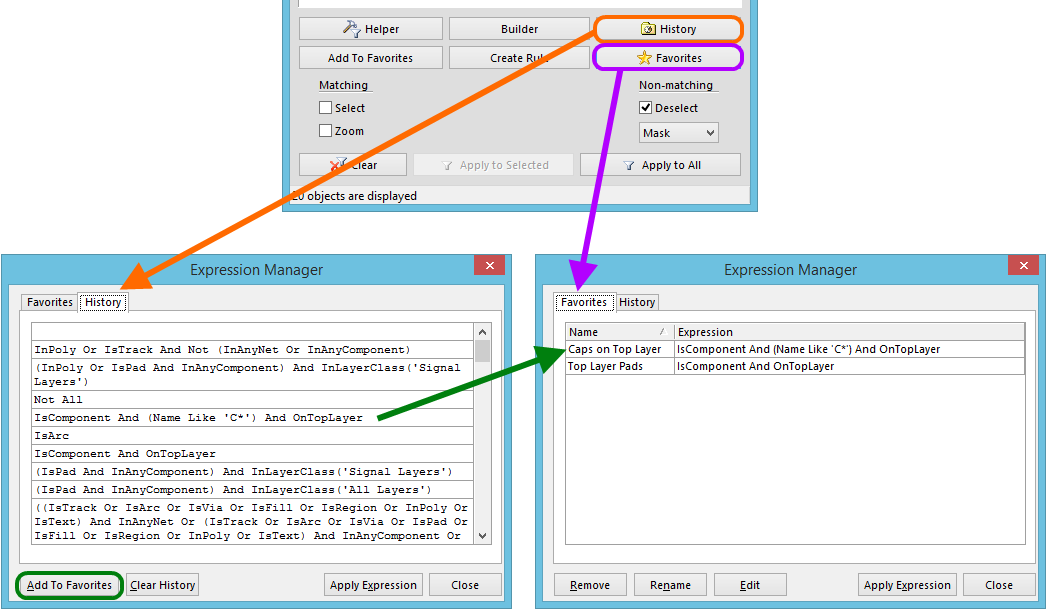
Access a history of applied query expressions and build a listing of favorite expressions to be reused time and again.
To use an expression in either list, simply double-click on its entry, or select its entry and click the Apply Expression button. The Expression Manager dialog will close and the expression will be loaded into the panel and applied automatically.
Creating Design Rules
The panel also provides the facility for creating a design rule, the scope of which uses the currently defined query expression.
To add a new design rule, click on the Create Rule button, located in the cluster of buttons beneath the filter expression window. The Choose Design Rule Type dialog will appear. This dialog lists each of the rule categories and rule types that are available in the PCB document. Simply choose the type of rule to be created and click OK (or double-click directly on the entry).
The PCB Rules and Constraints Editor dialog will appear. A rule of the chosen type is created and the main editing window for the rule is displayed, ready to define specific constraints for the rule. The query expression from the panel is entered into the Full Query region of the dialog.