Enhanced Output Path Definition in Output Job Files
Contents
Ever generated an output from an Output Job file and wondered why it didn't quite end up in the place you thought it would? Ever tried some bizarre workaround to get that pdf in the right folder? Ever been puzzled as to why your outputs never seem to go anywhere but an "Outputs for Project" sub-folder? Those days of bewilderment and frustration trying to lock in the required output paths are over. Altium Designer brings you a sleek, intuitive interface that makes output location definition a breeze. Brought in to primarily support the new Design Data Management system, with its high-integrity release process, this feature gives you total control over where generated output is stored, when using PDF, Folder Structure, or Video output containers.
Accessing Output Location Controls
Controls for defining the output location for an output container (by default, called New PDF, New Folder Structure, or New Video) can be found in the associated settings dialog used to configure that container. From within the Output Job Editor, access the dialog by clicking on the Change link for the container in the right-hand Container pane. Alternatively, right-click on the entry for the medium and choose Properties from the context menu.

Accessing output location controls, in this case for a PDF contianer.
Defining the Output Location
The output location – where the container will be created – is specified in the Output Management region of the container's settings dialog. The location consists of various stages, with each stage defined using a corresponding pop-up, accessed by clicking on that stage.
-
Base Path – this stage is used to define the 'root' of the output container. By default, this is set to
Options for defining the base path of the output location.[Release Managed], which means that the Design Data Management system will handle the base path automatically. The base path will depend on how you are using the PCB Release view. In Design Mode, the base path will be the\<ProjectName>\<ConfigurationName>folder, within your local working sandbox. In Release Mode, the base path will be the root folder of the Altium Vault referenced by the project configuration. You can also define a specific path by switching this stage to[Manually Managed]and specifying the path accordingly (which can be made relative to the design project).
-
Container Type Folder – this stage is used to define a sub-folder based on the type of media container being generated. It is completely optional as to whether you use this extra 'umbrella' folder or not. If you do, you can choose to have the system name the folder for you, using the container name or type (indication of the naming used is given in brackets). Alternatively, you can name the folder yourself.
Example of options for defining a container sub-folder for the output location.
-
Output Folder / Output Filename – the function of this stage depends on the output container type for which the output location is being specified. For
Example of options for defining an output filename or folder, depending on the output container type and output types.PDForVideocontainer types, this stage simply requires you to change the desired filename or you can leave it set by the system. The extension is automatically applied for you. If you have multiple PDF or video outputs and want them generated as separate files (as opposed to a single, merged PDF file or Video), you also have that option. If you choose to generate separate files you then also have the option of having each of them placed in it's own sub-folder, named automatically based on the output name or type. Alternatively, specify your own custom name. In this latter case, the entry you specify will be used as a prefix, and the folder will be named in the format<YourSpecifiedNaming>_[Output Type].
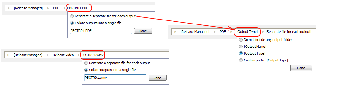
For the Folder Structure container type, this stage enables you to specify a folder for each generated output. As with the PDF or Video types, you can either opt to let the system name the folders for you, based on output name or type, or specify your own custom name. In the latter case, the entry you specify will be used as a prefix, and the folder will be named in the format <YourSpecifiedNaming>_[Output Type].
As you make changes to the individual stages comprising the output location, a preview of the resulting storage structure is displayed in the window below. This enables you to quickly zero-in on your preferred output folder structure.
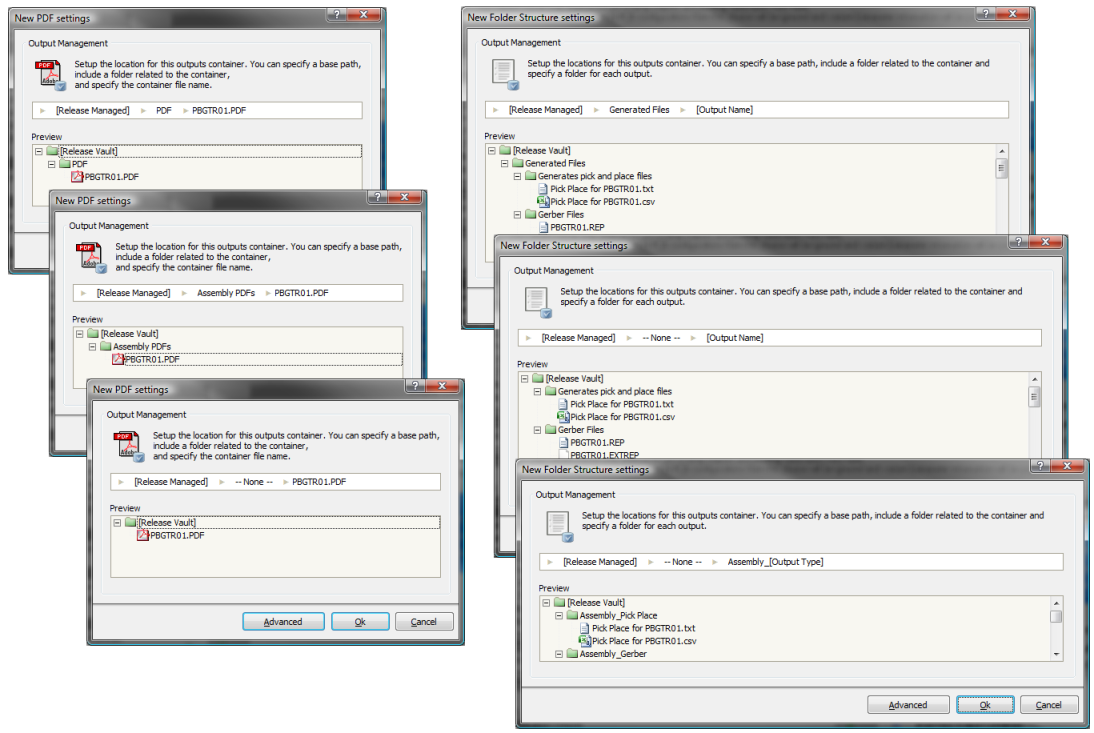
A preview of the output structure changes dynamically as you adjust each stage. Here, example changes to the output location are considered for both PDF (left) and Folder Structure (right) containers.
Viewing Current Output Container Paths
The current path definitions for all defined output container types can be seen in the Output Containers pane. As shown in the image below, each Release Managed output container has a corresponding Path in Vault defined for it. The Local Path shown indicates where, on the user's local computer, output files are physically created before they are committed to the Vault. Manually Managed containers simply show the Local Path where they are configured to save the generated outputs.
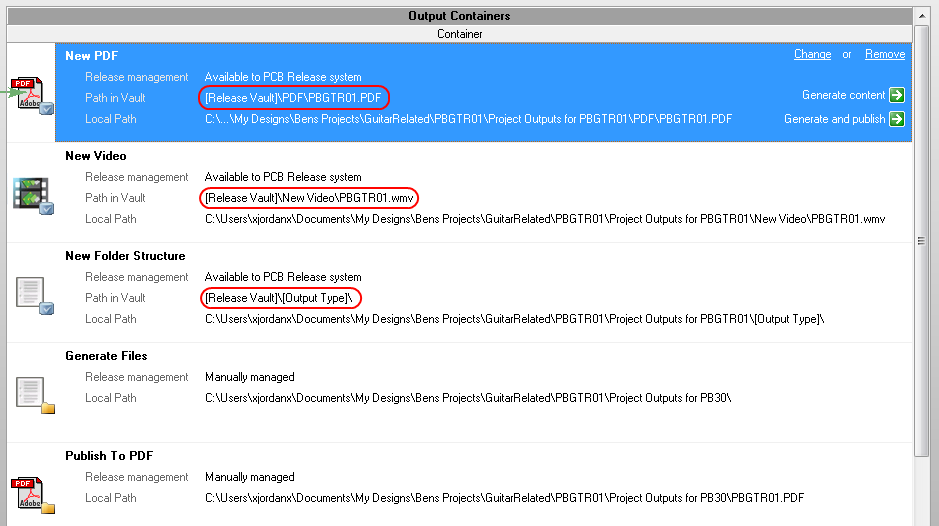
The current destination for output associated with each defined output container is reflected in the Output Containers pane.
Viewing Storage Structure from the PCB Release View
Related article: PCB Release View
When the base path of the output location for a medium is set to [Release Managed], the chosen structure is reflected not only in the previewing window, but also in the file generation region of the PCB Release view. In this way, you can always see how your outputs – generated from the PCB project configuration you are releasing – will be stored. If something is amiss, perhaps an output not going to the right location, simply open the associated Output Job file used to generate that output, and tweak the output location for the associated output container as required. You always have full control and full visibility prior to committing to, and initiating the actual release.
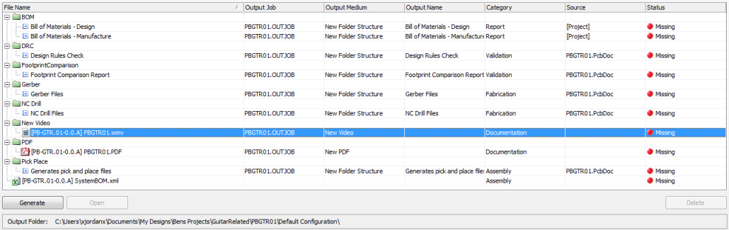
Verify that output locations are indeed as required from within the PCB Release view, prior to release.