ECAD - MCAD Integration
Altium's unique ECAD-MCAD integration environment allows designers the opportunity to import whole design concepts and complete their PCB board shape and height/volume restrictions with complete confidence. In effect, a PCB designer can work directly from the original CAD models defined from a source document which determines the whole product and incorporates a blank of the desired PCB shape complete with mounting holes, cut-outs, etc.
By importing these definitive models, a PCB layout designer can even update according to revisions the source models may experience without having to revisit the procedure a second time. The models can be linked to their storage media path and the CAD revisions can be reflected in the PCB document.
From a design perspective, the source document embodies the outer casing - should it exist - and the internal dimensions which must be used to allow assembly of the finished product. When sourced designs are ready to be exported from a third party CAD tool, the step file can contain the nested hierarchy of an assembly - including the cases and associated hardware - along with a blank version of the PCB. In this way, Alituim's Winter 09 can import the entire model collection placed correctly with respect to each other and a common origin point.
The board and circuit designer can then create their board outline from the incoming blank supplied in the STEP file. Thereafter, the designer can place and route accordingly. The incoming originals would best be linked in the first instance - not embedded - so as to allow for easy updates to the project should the CAD design go through a series of revisions.
A variety of ways currently exist for the creation of 3D bodies. Within Altium Designer, extrusions from a shape or directrix are available and heights can be given. These objects can be combined in the component Library into a component assembly. Third party step models - no matter their originating software - can be imported as step files and placed either as part of footprint assemblies, or as free models in a PCB document.
In the end, there can be quite a variety of history behind the origins of different objects on a single board or assembly. This difference in origin should not be able to compromise the compliance of an exported Altium PCB STEP model with regard to third party MCAD software.
All edits to objects which reflect an actual change in the 3D screen will be exported in step. Solder resist layer is hard coded at 0.5 mils (thousandths of an inch) and does not alter. This places it above the zero (0) plane marker in most third party CAD elevation views as it is added to the thickness of the stack. In general, this would appear good practice but is a result of a WYSIWYG output of the board in 3D.
MCAD ECAD integration Case Study
One of the greatest benefits to this entire environment is the ability to hone a board shape and configuration to ensure that the overall design is physically correct in every respect. This process can begin with the very source documents which modelled the product in its entirety. To demonstrate this capability, this case study looks at a step by step proceudre to import MCAD files from a design source and end up with a board and modelling which can be shape revised without tedium.
The projects chosen for this study were the Developer Tools DT01 and DT02. The first priorities for compliance are Solidworks and PRO Engineer (Wildfire 4.0).
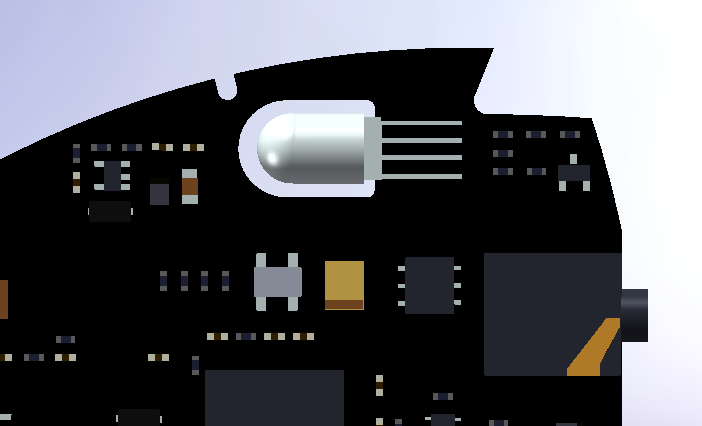
The test projects had their case and blank pcb formed in Solid Edge and the assembly contained within a single file. Winter 09 can then Place the Step model into a 'ready to place' PCB document. When the 3D Models listing is selected in the PCB Panel, the hierarchy of nested individual components in the file can be displayed. In this instance, the model is described as a Free model, i.e., it is not associated with a footprint.
The board shape can be defined under the Design menu by selecting Board Shape » Define from 3D body. The designer simply selects the model and then chooses which plane or face to use as the board shape.
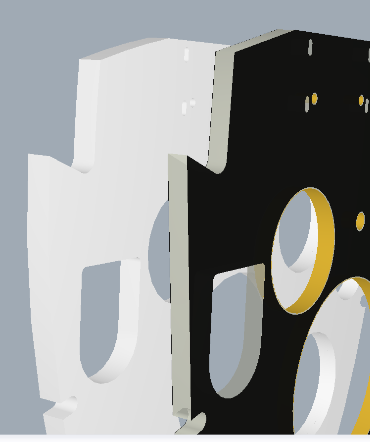
The board plane can be made to match that of the surface selected. ie, the top of the board can be made to align to the top of the blank model from which it was made. The original blank shapes in this case study were modified to simulate revisions and the exported Step file was used to create an update of the Altium imported model. This sequence can be followed by opening the properties of the current model and choosing to replace the old file with the newly revised Step models. This sequence can be automated if the file is linked as previously suggested. Should the linked file be overwritten, the PCB document in Altium Designer will prompt the user to update the current models.