Controlling the Color of Connection Lines
The connection lines that join the various nodes in each net are invaluable during the routing process, to help guide you as you route across and through the board. When the design is initially transferred all connection lines are given a default color, which can then be edited.
Changing the Connection Line Color
An easy way to make important nets stand out during the routing process is to change the color of their connection lines. To do this, double-click the net name in the PCB panel to open the Edit Net dialog, where you can edit the connection line color (set the panel to Nets mode). To change the color for multiple nets first select the required nets in the PCB panel, then edit the color of the selected nets in the PCB Inspector.

Displaying Connection Lines using the Layer Colors
As well as setting the connection line color for individual nets, you can also display the connection lines using the colors of the start and end layers that the connection line travels between. These connection lines are displayed as dashed lines, using the colors of both the start and end layers. This feature is ideal when you are routing a multi-layer board, as it you can easily tell the target layer that connection being routed must get to. Note that this dashed color override is only applied to nets that travel from one layer to another, if the connection starts and ends on the same layer it retains its defined color.
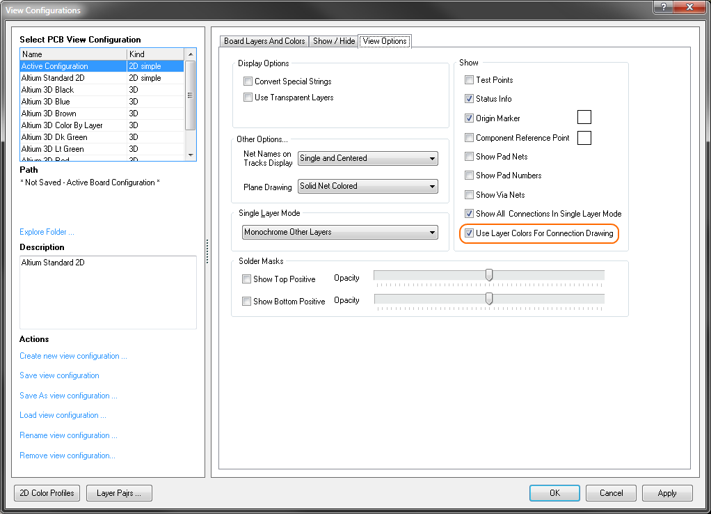
To use the color-by-layer feature, enable the Use Layer Colors for Connection Drawing option in the View Options tab of the View Configurations dialog, as shown below (click to enlarge).
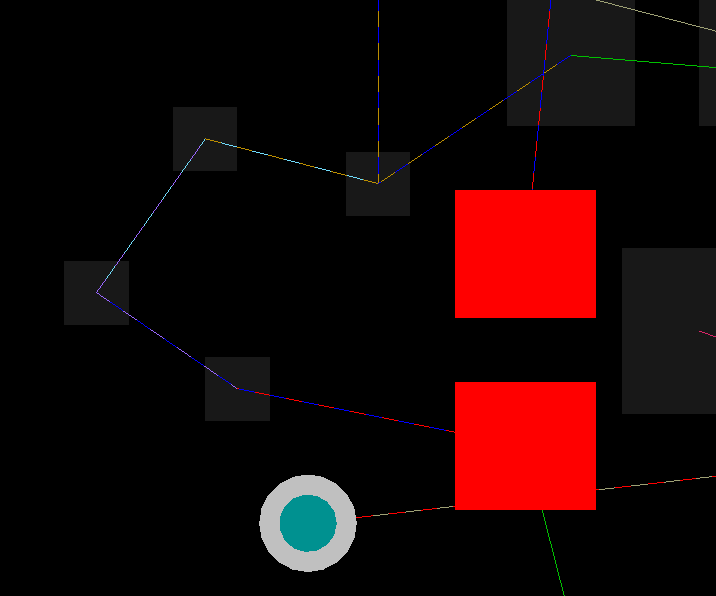
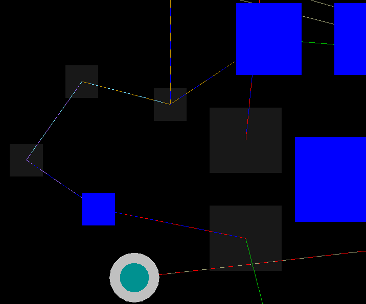
The images below show the same region of the board in single layer mode, firstly from the Top Layer, then from the Bottom Layer (click to enlarge).
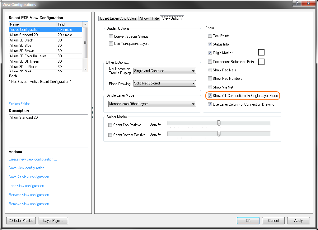
Displaying Connection Lines in Single Layer Mode
A multi-layer board is visually dense, making it difficult to interpret what is going on. To help with this, you can easily switch the layer display from the chosen Layers to Single Layer mode, by pressing the Shift+S shortcut. Normally, when you do, all connection lines that do not either start or end on the current layer are also hidden, as it is assumed that they are not relevant. To always display the connection lines, enable the Show All Connections in Single Layer Mode option in the View Options tab of the View Configurations dialog, as shown below (click to enlarge).