Technology Aware xSignals Wizard
Contents
Released in Altium Designer 15, the xSignals Wizard simplifies the process of creating multiple xSignals between multiple components, as a single process.
The xSignal Wizard creates xSignals between a single source component and multiple target components. The Wizard uses a component-oriented approach to identifying potential xSignals - you select a single source component, the nets of interest and the target components - it then analyzes all potential paths from the source component to the designation components, passing through series passive components and along any branches. As the designer you then get to choose the xSignals you would like to have generated, and you can also create Matched Lengths design rules targeting these xSignals.
The original xSignals Wizard supported creating custom xSignals for multiple components. The Wizard is being expanded to automatically create xSignals and xSignal classes for a number of different common interface and memory circuits. The first circuit-type to be added is DDR3/DDR4.

On Board DDR3 / DDR4
Select On-Board DDR3 / DDR4 to create xSignals for your DDR3 or DDR4 memory. In this mode, the wizard will automatically create the xSignals, xSignal Classes, Matched Length Groups, Diff Pair Matched Lengths rules and Fly-By topology for on-board DDR3/4. The Wizard assumes that a fly-by routing topology will be used.
The page includes settings for the width of the data bus, in each byte-lane. It also includes settings for the tolerance of the Matched Net Length rules that will be created for the:
- Address/Command/Control nets
- Data Byte-Lanes
- Clocks
The displayed settings are initial defaults. User-defined settings are saved for future use.
Selecting the Souce Components
On the next page, the Wizard identifies all potential source components and target components, based on the designator prefix and the number of pins.
- Set the Controller and Memory Devices designator prefix, and the Min Pin Count as required, for both the Source Component and the Target Components, then
- Select a single source component, then
- Select the target component(s).
Identifying the Address Group Nets
The next stage is to identify all of the nets that belong in the Address Group.
The functionality of this page is as follows:
- Fly-By Topology and T-Branch Topology options are supported, select the required topology from the drop down list.
- If Fly-By Topology is chosen (as shown above) the target devices are listed in the Point-to-Point order of the fly-by routing. The software will attempt to determine the order automatically. If Wizard is run before component placement, then the point-to-point order will need to set manually using the dropdown controls.
- If T-Branch Topology is chosen, half of the target devices will be shown before the source, and half after. Use the dropdown controls to order the target components as required.
- User-defined Class name syntax:
- The starting default is
ADDR_PP[#] - The
[#]represents the number of memory devices. - The
PPsuffix can be changed if required.
- The Wizard analyzes the components and looks for these suffixes in the design and displays the full name syntax, using the approach detailed below. Update these if they are not correct.
- The objective here is to automatically find the nets that correspond to these functions. Once the nets are found, the naming syntax is entered into the fields.
- The nets between the components are then reviewed, once the suffix is found the prefix is identified. For example, the Wizard looks for
_A[#]to locate the Address lines. - If no nets are found with a suffix that begins with “_”, it then looks for just the text after the “_”. Alternative separators, such as “-” or “.” are also checked for.
- If the syntax cannot be automatically determined, these fields must be defined by the designer. Use the dropdowns to select from the existing nets on the board.
- Once the order and the naming syntax has been defined, click the Analyze Syntax and Create xSignal Classes button to build the list of xSignals. The Wizard will look at the syntax and how the components are connected, and form the xSignal Classes, as shown in area marked by a 6 in the image above. The number of Classes created will match the number of memory devices.
- The number of classes created (eg 2) and the number of xSignal nets in each class (eg 25).
- The xSignals are grouped in a column for each xSignal class. A Matched Lengths design rule will be created for each class. The
U20-U41andU20-U40sub-headings represent the source and target components for these xSignals.
- If the automatically generated list is incomplete or incorrect, click the Modify Nets in xSignal Classes button to manually add or delete nets to/from a class. Note that manual changes will be lost if the Analyze Syntax and Create xSignal Classes button is then clicked again.
Identifying the Data Group Nets
The final stage is to identify all of the nets that belong to the Data Group.
The functionality of this page is as follows:
- User-defined xSignal Class name syntax.
- The starting default is
DATA_BL[#] - The
[#]represents the number of Byte-Lanes, which is determined by the total number of Data lines divided by the Data Bus Width defined earlier. - The
BLsuffix can be changed if required.
- The Wizard analyzes the components and looks for these suffixes in the design, then displays the full name syntax. Use the dropdowns to update these if they are not correct.
- Once the naming syntax has been defined, click the Analyze Syntax and Create xSignal Classes button to build the list of xSignals. The Wizard will look at the syntax and how the components are connected, and form the xSignal Classes, as shown in area marked by a 6 in the image above. The number of Classes created will match the number of Byte-Lanes connected to the memory devices.
- The number of classes created (eg 4) and the number of xSignal nets in each class (eg 11).
- Matched Lengths design rules are created for these xSignal Classes. The
U20-U41andU20-U40sub-headings represent the source and target components for the Byte-Lane xSignals.
- Click the Create Spreadsheet button to generate an XLS-format spreadsheet of the xSignals created by the Wizard.
xSignals and xSignal Classes Created
The Wizard automatically creates xSignals and xSignal Classes for the:
- Address xSignals detailed on the Address Group page - in the example image there are 2 xSignal classes created, with 25 xSignals in each (15 address nets, 3 bank address nets, plus the other: select, clock DiffPair, enable and strobe nets, as shown).
- Data xSignals detailed on the Data Group page - in the example image there are 4 xSignal classes created, with 11 xSignals in each (8 data nets, mask, and strobe DiffPair nets, as shown).
Design Rules Created
The Wizard then creates Matched Length design rules for:
- Each of the xSignal classes identified and created by the Wizard. In the example images above, there were 2 address xSignal classes, and 5 data xSignal classes. These rules will use the Group Match Lengths Constraint mode, where the length of each targeted object is compared to length of the longest object in that set, and the difference between their lengths must be within the specified Tolerance for the rule to be passed.
- For all of the Differential Pairs included in the xSignal classes created by the Wizard. In the example above, there are DiffPair clock signals included in the address xSignal classes, and also DiffPair strobe signals in the data xSignal classes. This rule will use the Within Differential Pair Length Constraint mode, where the lengths of the members in each targeted pair are compared to each other, and must be within the specified Tolerance for the rule to be passed.
The rules use the Tolerance constraint entered into the second page of the Wizard. Adjust the tolerance if required.
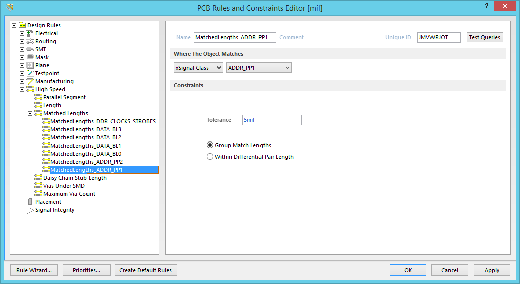
A Matched Length design rule is created for each xSignal class created by the Wizard.
If there are differential pairs, an additional Matched Length rule is created targeting those pairs, defining the allowed tolerance between members in the pair. Adjust the tolerance if required.
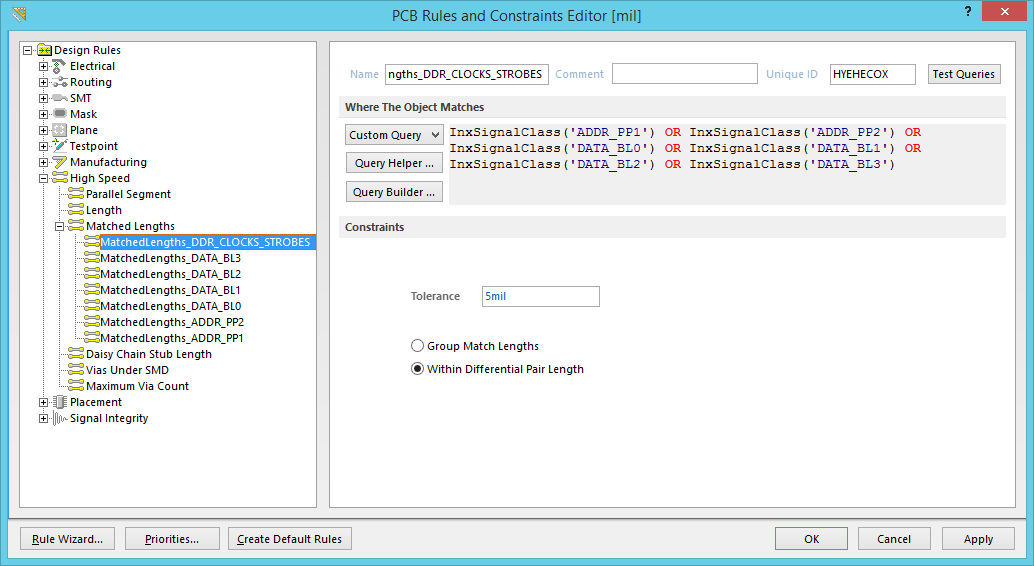
A single Matched Length rule is created for differential pairs, with a scope that targets each xSignal class that includes a differential pair.