Ibis Model Implementation Editor
Altium Designer has long had the ability to use IBIS models for enhanced modeling of IC pins when performing Signal Integrity analysis. However, their use has always required importing them into Altium Designer's own Signal Integrity model format (referred to as SI Macro Models).
To support third party tools that require dedicated IBIS models for their Signal Integrity simulations, and cannot use Altium Designer's own model format, Altium Designer 14.0 introduced a dedicated IBIS model implementation editor, allowing the IBIS model to be attached to the schematic component.
This feature was exended in Altium Designer 15, with the addition of support for using attached IBIS models with Altium Designer's own internal Signal Integrity analysis engine.
Now you can either:
- Import the IBIS pin models into the component pins during Signal Integrity Analysis (to be stored as Altium Designer SI Macro Models), or
- Attach the IBIS model to the schematic component, as described in this page.
Accessing the IBIS Model editor
Access the implementation editor for this model type anywhere that models can be defined for a schematic component:
- From the Models region of the Sch Library panel.
- From the Models region of the Schematic Library Editor workspace.
- From within the Model Manager dialog (in the Schematic Library editor).
- From the Models region of the Properties for Schematic Component dialog.
In each case, simply click Add and choose the IBIS Model entry from the associated menu. The IBIS Model dialog will appear.

Add a dedicated IBIS implementation model to a schematic component using the IBIS Model dialog.
Defining the model link for an IBIS model is, for the most part, similar to that for a PCB 2D/3D component model, and is described in the following sections.
IBIS Model
Specify the name for the model – exactly as it appears within the .ibs file – and give the model link a meaningful name, perhaps describing what the implementation in this domain represents.
Alternatively, and especially if you are unsure of the name, use the Browse button to access the Browse Libraries dialog. Use this dialog to browse IBIS model files across all currently Available Libraries (Project libraries, Installed libraries, and libraries found along specified search paths). Use the Find feature in this dialog if the required model files are not part of the currently Available Libraries.
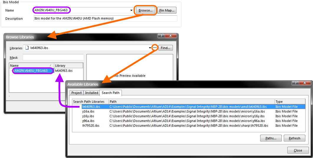
Specify the name of the model directly, or browse for it.
The mapping of schematic component pins to IBIS model pins is defined in the Model Map dialog, accessed by clicking the Pin Map button.
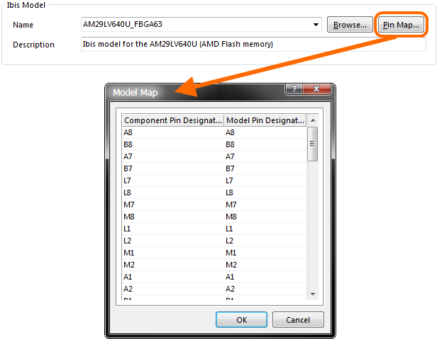
Verify component-to-model pin mapping in the Model Map dialog.
IBIS File Location
Options are available in this region of the IBIS Model dialog with which to specify how the software is to locate the model – provided the model name is defined:
- Any – all Available Libraries (project libraries, installed libraries and libraries found along defined search paths) are used to look for the model.
- File name – enter the full file name in which the model resides (e.g.
ThisFile.ibs). All Available Libraries are used to look for the model. If not found here, the default library path (Library Path field on the System – Default Locations page of the Preferences dialog) will be interrogated to see if the named file can be found there. - File path – enter the full path/name of the file. Click the Choose button to browse to the file. This option will always find the model, since it is explicit (provided of course the file remains in that directory!).
- Integrated/Database Library – post-placement, if the component is placed from an integrated or database library, the model can be sourced directly from that same library, provided the library is part of the Available Libraries set.
If successfully located, indication of where the model was found will be presented.
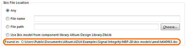
Specify how to find the IBIS model.
Pin Models
This region of the dialog present a view-only listing of the pin models defined for the chosen IBIS model. You can however change the Model Type from the default Typical Case, to either Strong Case or Weak Case respectively.

Pin Models for the chosen IBIS model.
Model Selectors
The Model Selectors region of the dialog will be populated if the chosen IBIS model has model selectors in it. This allows you to choose which model to use (e.g. a pin might have models for different voltage levels; 3.3V, 5V etc).
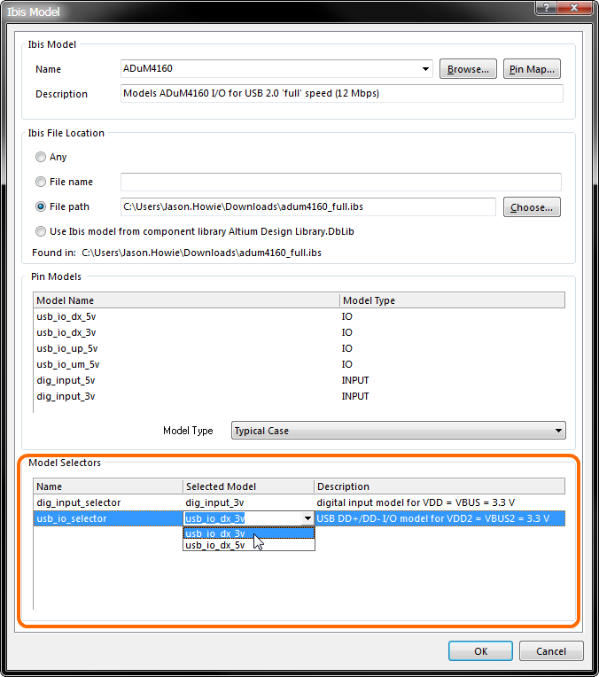
Example IBIS model with defined model selectors.