How it Works - Configurations and Constraint Files
There are 3 classes of configuration information that need to be defined as constraints. These are:
- Specific to the Device and Board - the pins used on a given device, on a given board.
- Specific to a Certain Device - including specifications for how to use internal features of the particular device.
- Specific to a Project or Design - includes requirements such as the allocation of a clock resource, and the speed it must run at.
All three are implemented as constraints within constraint files. Constraint files can contain any number of different constraints, for any of the classes mentioned above. To ensure the most portable FPGA design, the most logical approach is to break the constraints into these three classes and store them in separate constraint files.
Sets of constraint files are targeted to a design by creating a configuration, which is simply a named list of constraint files. For example, consider an FPGA project that is targeted to:
- a Xilinx Spartan-XC2S300E QFP208 on a NanoBoard
- an Altera Cyclone QFP240 on a NanoBoard
- and a Xilinx Spartan-XC2S100E QFP144 on the user's own board design.
This would require three configurations – one for each target.
Assuming good design practice (from a portability perspective) this would theoretically require seven constraint files:
- 3 separate constraint files to control the pin-outs for each of the three devices in their target boards,
- 3 separate constraint files to control any internal place and route constraints for each of the three target devices, and
- 1 constraint file for logical design constraints.
If there were no place and route constraints (which would usually be the case), then there would only be four constraint files.
Each configuration would then include three constraint files, two which are specific to the configuration and one which is common to all configurations.
If there were constraints that were common to the two different Xilinx devices (which are internally very similar) then it may be beneficial to create a constraint file for these. In this case, the extra constraint file would be added to two of the configurations.
Diagrams of these Example Configurations and their Constraint Files
Figure 1 shows the relationships between the constraint files and the configurations for the examples described above.
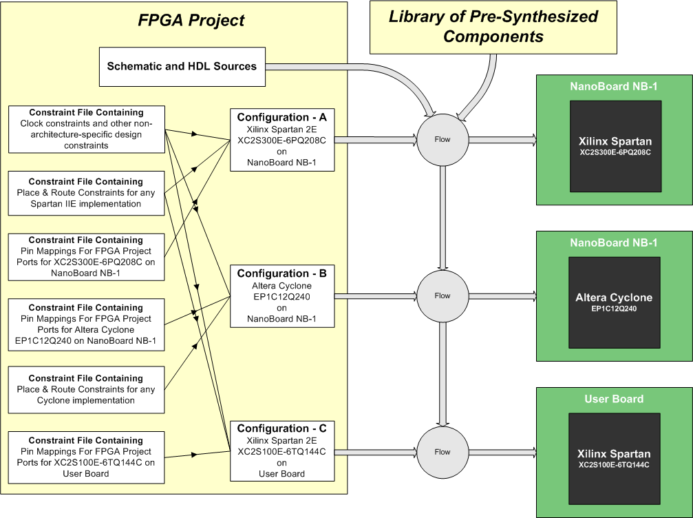
Figure 1. A single set of schematic and HDL source documents, targeted to three different implementations by different sets of constraint files.
The actual setups for each of the three configurations are as follows:
For the Spartan 2E300 on the NanoBoard
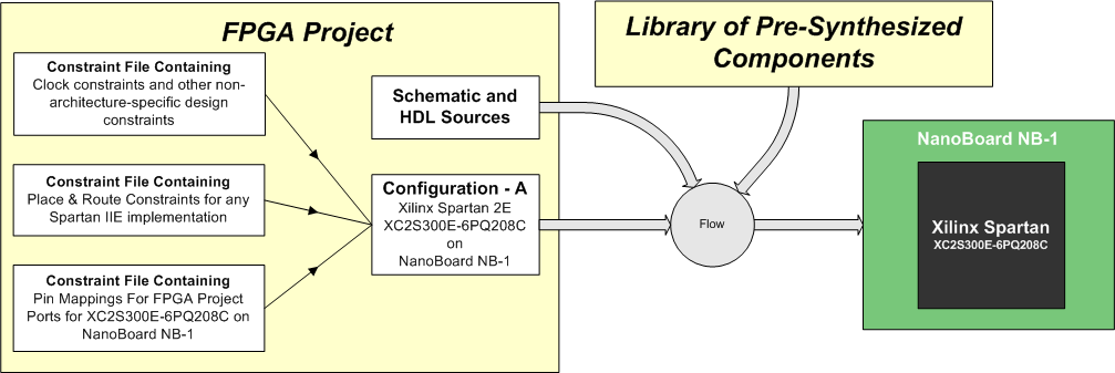
Figure 2. Design targeting a Xilinx Spartan2E 300, on the NanoBoard.
For the Cyclone EP1C12 on the NanoBoard
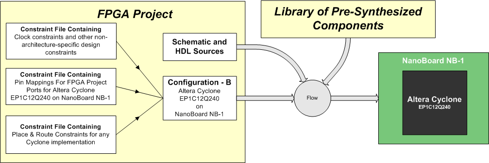
Figure 3. Design targeting an Altera Cyclone EP1C12, on the NanoBoard.
For the Spartan 2E100 on a User Board
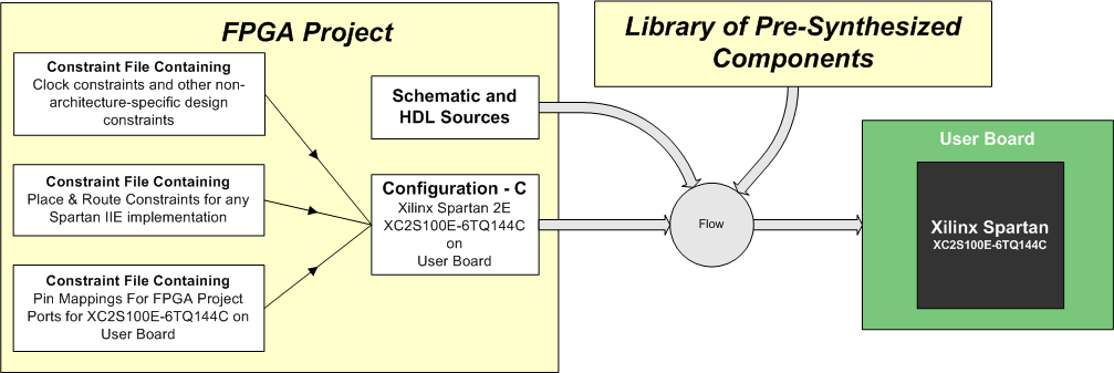
Figure 4. Design targeting a Xilinx Spartan2E 100, on a User Board.
Using Configurations
Configurations and constraint files can be considered from two different perspectives.
Existing Board
In the case where the FPGA designer is working with an existing (constructed) PCB, the resources of the board and how they are connected to the FPGA are already defined. This would include Altium NanoBoards and third party development or evaluation boards. The board would come with a constraint file that describes its resources and how they are connected. In the case of boards with plug-in devices, the board would come with a number of constraint files, one for each plug-in device.
New Board being Developed
In this case, the design of the FPGA may be driving the design and layout of the PCB. Here the designer may let the FPGA tools allocate pins for the design and then use this information to drive the layout of the PCB. Alternatively, the PCB designer may allocate the pins on the FPGA and then pass this information to the FPGA designer.
In all of these cases, a constraint file holds the current assignments of these pins. This information is used to update either the PCB design or to drive the FPGA place and route tools. The information in this file can also be updated by importing from the FPGA tools, or importing from the PCB design after board-level optimization of pin assignments.
An Iterative Approach
These two perspectives should not be considered as mutually exclusive. With the first case of an existing constructed board, there will most likely (in the case of NanoBoards and other development boards) be general purpose I/O headers that can be used as required. In this case, the constraint file that comes with the board should be considered as a template for the engineer's own design. The constraint file could be extended to include the engineer's new connections through the general purpose I/O connectors on the board, or an extra constraint file could be created to hold this information.
Defining a Configuration
A configuration is essentially just a named list of constraint files. Configurations belong to the project, and are stored in the project file. Configurations are created and managed in the Configuration Manager dialog, accessible through the Project menu.
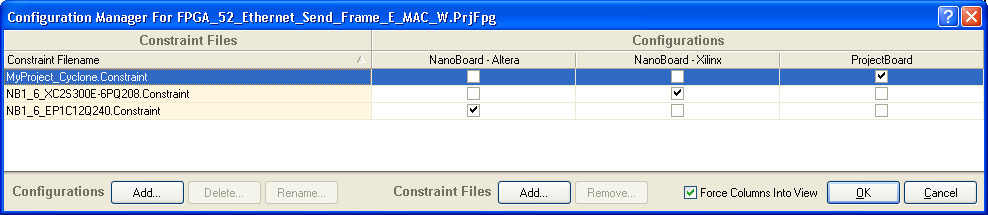
Managing configurations and constraints through the Configuration manager dialog - this project also has 3 configurations.
Controls in the Configuration Manager dialog allow the creation of new configurations, and the allocation of constraint files to a configuration.
Understanding Constraints
Main article: Constraint File Reference
Constraint files are simple documents within the system and can be compiled to add more intelligence to the whole process.
A constraint document contains a list of statements, known as constraint groups, each of which targets one or more objects and contains one or more constraints.
The following example constraint group, shown in the typical constraint group syntax, specifies the target FPGA device:
Record=Constraint | TargetKind=Part | TargetId=XC2S300E-6PQ208C
Each constraint group can include multiple constraints, for example a constraint group can be added that targets a bus (a collection of nets). Multiple constraints can then be added to target the individual items within the bus. The file syntax of this would be:
Record=Constraint | TargetKind=Port | TargetId=DB[7..0] | FPGA_PINNUM=P8,P7,P6,P5,P4,P3,P206,P205 | FPGA_SLEW=FAST,FAST,FAST,FAST,FAST,FAST,FAST,FAST
This example specifies a set of constraints that target the Ports DB7..DB0. It then supplies eight FPGA_PINNUM constraints and eight FPGA_SLEW constraints.
Note that bus ports can be described in a constraint and then later, after compiling, these can be mapped to individual pins. There is no need to specify both levels (bus and single) as separate constraints.
Multiple constraints can target the same Port. For example the following constraint groups target the port CLK_REF; the first specifies the pin number, the second specifies that this pin must be configured as a clock pin, the third specifies that this net must use a global clock resource, the forth specifies that the place and route process should attempt to route this to achieve the specified frequency.
Record=Constraint | TargetKind=Port | TargetId=CLK_REF | FPGA_PINNUM=P185
Record=Constraint | TargetKind=Port | TargetId=CLK_REF | FPGA_CLOCK_PIN=TRUE
Record=Constraint | TargetKind=Port | TargetId=CLK_REF | FPGA_CLOCK=TRUE
Record=Constraint | TargetKind=Port | TargetId=CLK_REF | FPGA_CLOCK_FREQUENCY=50 Mhz
Alternatively, these constraint requirements could be specified in the one constraint group:
Record=Constraint | TargetKind=Port | TargetId=CLK_REF | FPGA_PINNUM=P185 | FPGA_CLOCK_PIN=TRUE | FPGA_CLOCK=TRUE | FPGA_CLOCK_FREQUENCY=50 Mhz
A more appropriate way to group them would be a group of those that are design-type information, and another for those that are device-on-PCB type information, in separate constraint files. For example, the design-type constraint file would include:
Record=Constraint | TargetKind=Port | TargetId=CLK_REF | FPGA_CLOCK=TRUE
Record=Constraint | TargetKind=Port | TargetId=CLK_REF | FPGA_CLOCK_FREQUENCY=50 Mhz
And the device-on-PCB type constraint file would include:
Record=Constraint | TargetKind=Port | TargetId=CLK_REF | FPGA_PINNUM=P185
Record=Constraint | TargetKind=Port | TargetId=CLK_REF | FPGA_CLOCK_PIN=TRUE
Note that they have been kept as separate entries in the constraint files for readability.
For information on the constraint system in place for the Desktop NanoBoard, see Understanding the Desktop NanoBoard NB2DSK01 Constraint System.
Transferring the FPGA Design to the target PCB
Implementing a design into an FPGA on a PCB is done in the Devices view. Here the FPGA project, in combination with a configuration, is targeted to a board. An example is shown in the image below.

The one FPGA project (RateController) is targeted to different FPGAs, each on a different board, by two separate configurations.
For the Configuration to be valid, it must include:
- at least one constraint file
- a constraint group in the file specifying the same device as the one available on the target board.
When the Live option is enabled the system searches for a physical device that matches the device specified in the project configuration and assigns that project to that FPGA/board. If there are no valid configurations available in the project, you will not be able to select an FPGA project/configuration in the drop-down list.
Synchronization of the FPGA Design to a PCB
Since the FPGA design is target-independent, the synchronization process actually happens between the constraint file and the PCB project, rather than the actual design captured in the FPGA project source files.