The task of creating a component library symbol and its pin data has become an increasingly involved undertaking as components have advanced in complexity. With current large scale BGA devices requiring the placement and configuration of hundreds of pins for example, substantial time and effort is often required to create viable component symbols.
To ease the workload associated with creating component symbols, Altium Designer now offers an advanced Schematic Symbol Generation Tool based on a symbol wizard interface and pin editor dialog. This features automatic symbol graphic generation, grid pin tables and smart data paste capabilities.

The Symbol Generation tool is provided as an Altium Designer software extension, which must be installed to enable the tool’s features.
To install the extension, select the Purchased tab in the Extension Manager (DXP » Extensions and Updates) and locate the Schematic Symbol Generation Tool icon in the Software Extensions category. Click its ![]() icon to download and install the extension, and then restart Altium Designer to enable the extension’s functionality.
icon to download and install the extension, and then restart Altium Designer to enable the extension’s functionality.
Once installed and ready to use, the extension will appear under the Extension Manager’s Installed tab.
Creating a Symbol
The Schematic Symbol Generation Tool becomes available when a Schematic Library document is open, and is instigated from Altium Designer's Tools menu – Tools » Symbol Wizard.
To create a new component symbol using the Symbol Generation Tool, first add a new library component using the Add button in the Component section of the SCH Library panel. The new symbol can then be developed through the Symbol Generation Tool (Tools » Symbol Wizard) which opens as the Symbol Wizard dialog.
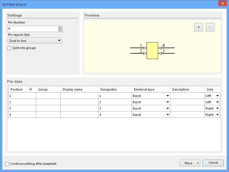
The Symbol Wizard dialog contains three main sections – Settings, Preview and Pin data.
Settings
The dialog's Settings options determine the basic configuration for the symbol, including its layout style and number of pins.
The Pin layout style allows you to choose from a set of predefined symbol patterns, where the pin positioning is automatically assigned. Use the drop down menu to select the preferred arrangement – the result will be visible in the Preview image and the Side column settings in the Pin data table.
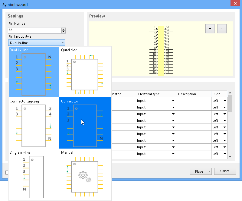
Note that the Pin layout style options include a Manual configuration, where pin positions are not automatically assigned. The layout style will revert to this setting when the pin positioning of a standard style (Quad, Zig-zag, SIL) has been edited.
The Split into groups Settings option provides both visual and tabular separation of pins assigned to a common Group setting in the table.
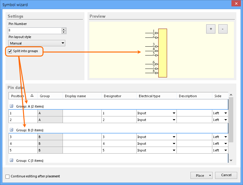
This configuration is useful for large (or multi-part) components where pins can be combined into functional groups or interfaces. Grouped pins are collected in a collapsible tree arrangement in the pin table.
Preview
The Symbol Wizard dialog’s Preview screen contains a view of the symbol graphic which dynamically represents the current settings and pin data.
Use the ![]() and
and ![]() buttons to control zoom, and Right-click + drag to adjust the positioning of the zoomed view.
buttons to control zoom, and Right-click + drag to adjust the positioning of the zoomed view.
Pin data
The dialog’s Pin data section provides an advanced table editor for pin data, which features multi-cell editing and column mapping Smart Paste capabilities.
The table grid columns are:
- Position – The (not editable) reference position index of a symbol pin.
- Group – A manually entered string used to define a collective group of pins.
- Display name – The component pin’s Display Name attribute string.
- Designator – The pin’s Designator attribute string, which will automatically match the pin Position number by default.
- Description – A pin’s Description string attribute.
- Side – A drop down menu list offering a selectable pin position on the symbol sides faces (left, top etc). When edited, the Pin layout style setting will change to Manual.
- Electrical Type – drop down menu list offering selectable electrical types (input, output, passive etc) for a pin.
Click on a column heading to order the table data by that column – click again to toggle the order between ascending and descending.
Pin data table cells can be manually edited on a single or multiple basis – use standard Ctrl + click and Shift + click techniques for the latter. To edit multiple cells in columns that feature drop down menus, select the desired cell range then make the new menu selection on one of the selected cells.
Pasting pin data
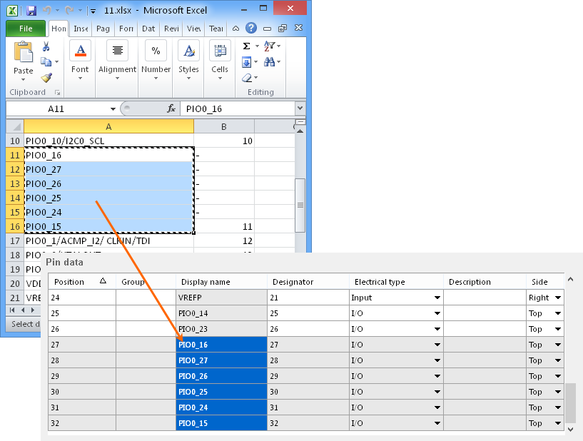
While the pin data in the table can be edited to a common value for multiple cells, the dialog's Paste and Smart Paste features provide an advanced way to populate all cell data by bringing in large amounts of different data from external sources.
Within the table, standard copy and paste techniques can be used to populate data from one group of cells to another. For example, by select three cells in a column, copying the data (right-click – Copy), then selecting three target cells to paste to (right-click – Paste).
The same technique can be used to copy a data selection from an external source, such as a spreadsheet, text or PDF file.
Smart Paste
Beyond standard copy and paste techniques, Smart Paste offers the capability to populate multiple columns of data from an external source using an automated column mapping approach.
To copy several columns of source data into matching columns in the pin data table, right-click in the table and select Smart Paste from the context menu. This opens the Pin Data Smart Paste dialog, which will be populated with the source data – in this case, a copy of multiple columns in a pin data spreadsheet. A range of data delimiters are available, which can be selected to match the delimiters used in the source data.
Each column of data in the dialog offers a drop down heading menu, which provides a choice of column names that are available in the pin data table. Select the appropriate data column heading name to match the data content, so that this will be mapped into the correct Pin data table columns.
Once satisfied with the column data to heading matches, click the Paste button to finish the process,
The completed symbol and pin data can then be placed as a component, or as one section of a multi-part component, using the dialog's Place button. Note that if the Continue editing after placement box is checked, the Symbol Wizard dialog will remain active (allowing further editing) once the component has been placed.