Presenting a Rigid-Flex Design in 3D
Contents
Altium Designer includes a powerful 3D rendering engine, which allows the presentation of a highly realistic 3 dimensional representation of the loaded circuit board. This engine also supports rigid-flex circuits, and when it is used in combination with the Fold State slider allows the designer to examine their rigid-flex design in the flat state, the fully folded state, and anywhere in between.
Displaying and Folding a Rigid-Flex Design in 3D
To switch to the 3D display mode, press the 3 shortcut key (press 2 to return to 2D, or 1 to return to Board Planning Mode). The board will be displayed in 3D, and if the component footprints include 3D Body Objects that define the mounted component, then these will also be displayed. In the image below you can see that the board includes a battery and a battery clip.
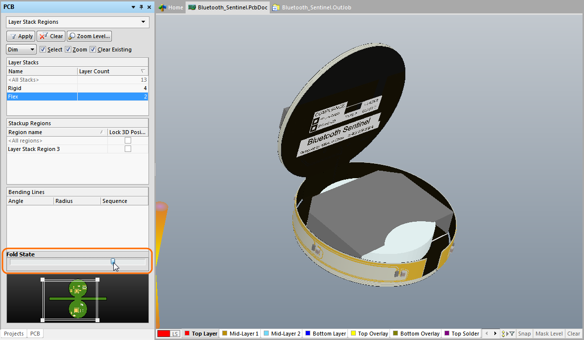
To apply all of the Bending Lines, slide the Fold State slider - it's in the PCB panel when set to Layer Stack Regions mode - as highlighted in the image below. Note that the bends are applied in the order defined by their sequence number. Bending Lines can share the same sequence number, it simply means that those bends will be folded at the same time when the Fold State slider is used. The board can also be folded/unfolded by running the View » Fold/Unfold command (press the 5 shortcut).
3D Movie Maker Support for Rigid-Flex Designs
Main article: PCB 3D Video
The ability to fold a rigid-flex design can also be captured as a 3D movie. It is very simple to do and does not require the use of movie key frames during the folding sequence.
Refer to the main article referenced above for a detailed description of how to make a 3D movie. As a basic guide:
- Switch the PCB editor to 3D mode.
- Display the PCB 3D Movie Editor panel, and create and name a new Movie Title in the top section of the panel.
- Create an initial Key Frame, showing the board in its unfolded state.
- Slide the Fold State slider to show the rigid-flex design in its folded state, then position the folded board as required.
- Now create a second Key Frame for this view, and set the time. Consider how long you want it to take to fold the rigid-flex design (the Duration setting), typically this would be a few seconds.
- To check that the video captures the folding process correctly, press the Play button
 .
. - To generate a movie file, add a PCB 3D Video Documentation Output in an Output Job file. Remember to configure the video format options in the Video settings dialog.
- Click the Generate Content link the Output Job file to create the movie file.
The video shown below was created using this process, it has the 2 key frames described above, plus 1 additional key frame that was added at the end to hold the final position for a second.