Contents
As more and more electronic products involve both electrical and mechanical components, and product release cycles get shorter, there's a real need for stronger collaboration between the ECAD and MCAD domains. But that collaboration isn't always smooth. The electrical designer and mechanical designer often send emails back and forth, or have to dabble in each other's respective design tools – something that leaves them treading a little water, and far removed from their established comfort zones. The solution is to use a method of collaboration that enables the two to graphically communicate ideas and proposals for change, without leaving their trusty working environments. Such a method is provided through ProStep's Electrical Design, Mechanical Design (EDMD) standard for data exchange, that is based on XML protocol. This collaborative standard is often simply referred to by the name of the exchange file format – IDX (Incremental Design Exchange format).
With this intermediate exchange file (*.idx), an electrical designer can export only changes to the board design that are needed (and of value) by the mechanical designer. Conversely, the mechanical designer can float change proposals back to the electrical designer, who can then import those changes back into their design.
Support for this standard of collaboration between ECAD and MCAD domains is available in Altium Designer, courtesy of the Mechanical CAD Collaboration extension. This extension allows you to incrementally exchange data between Altium Designer and mechanical CAD applications (such as SolidWorks), using the ProStep EDMD exchange format. Functionality includes support for change requests, as well as the transfer of Cu geometry.
Extension Access
The Mechanical CAD Collaboration extension (a Software Extension) can be found on the Purchased tab of the Extensions & Updates view (DXP » Extensions and Updates).

The Mechanical CAD Collaboration extension.
Initiating the Baseline EDMD File for Collaboration
Collaboration can be kicked off from either direction – so either the electrical designer creating the initial ProStep EDMD file, or the mechanical designer doing the honours. If the electrical designer does so, the file created is called the ECAD Baseline file (ECAD Baseline.idx), which is subsequently made available to the mechanical designer. If the mechanical designer does so, it is called the MCAD Baseline file (MCAD Baseline.idx), which is subsequently made available to the electrical designer.
Exporting from Altium Designer (ECAD Creation of Baseline)
From within Altium Designer, the main interface for collaboration is the Mechanical CAD Collaboration panel, accessed by clicking the PCB button ![]() at the bottom-right of Altium Designer when the PCB Editor is active, and selecting the Mechanical CAD Collaboration entry from the pop-up menu.
at the bottom-right of Altium Designer when the PCB Editor is active, and selecting the Mechanical CAD Collaboration entry from the pop-up menu.
To initiate collaboration, simply click the Export Baseline button. You will be presented with the Export EDMD Baseline dialog, which offers options including the export of copper objects.
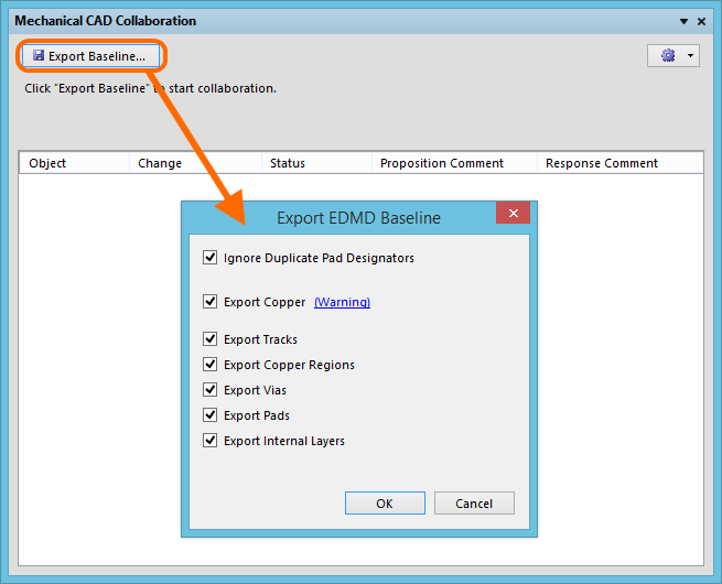
Initiate collaboration from within Altium Designer by creating the ECAD Baseline.
Importing to Altium Designer (MCAD Creation of Baseline)
If the baseline file has been created on the MCAD side, it can be imported into Altium Designer using the File » Import MCAD IDX Baseline command. The Import MCAD Baseline dialog will appear. Use this to browse to, and specify the MCAD Baseline file (MCAD Baseline.idx), and the PCB document into which proposed changes are to be synchronized.
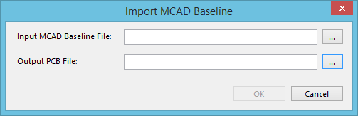
Accept collaboration from within Altium Designer by importing the MCAD Baseline.
Collaboration Folder
When initiating collaboration from Altium Designer (creating the EDMD Baseline file), a collaboration folder will be created under the original board design project. The folder is named using the PCB document name, in the form PCBDocumentName.PcbDoc_EDMD. The folder will contain two files:
- AD_EDMD_State.xml
- ECAD Baseline.idx
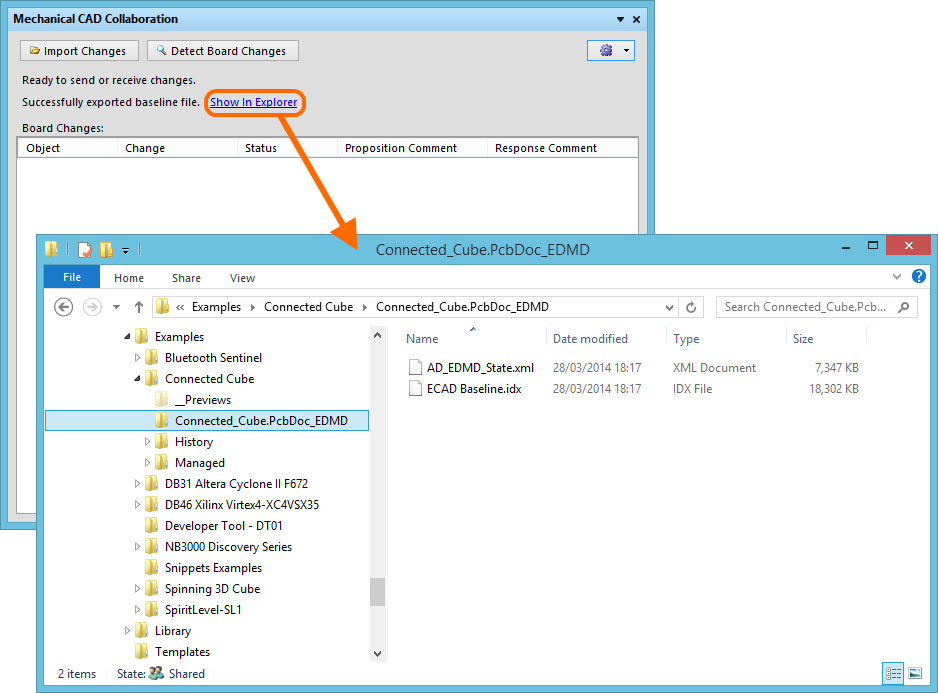
Creation of the EDMD folder and baseline file.
Synchronizing Changes
The Mechanical CAD Collaboration panel provides controls for keeping changes synchronized between the ECAD and MCAD domains. Changes are proposed through EDMD Changes files:
- If the mechanical designer has proposed some changes and sent them across in a new EDMD Changes file, the panel allows those changes to be received (imported) into the PCB design, for consideration.
- If some changes have been made to the board, the panel can detect these changes (except copper changes) and list them, ready for export to an EDMD Changes file, that is subsequently made available to the mechanical designer.
Detecting Board Changes
If you make a change to the PCB document, such as removing a component, that change can be detected by clicking the Detect Board Changes button, at the top of the Mechanical CAD Collaboration panel. The detectable changes will be listed in the Board Changes region of the panel, in terms of:
- Object - for example the component designator.
- Change - for example Removed for a component that has been removed from the design, or Added for a one that has been added.
- Status - which will be Proposed since the change is originating on the ECAD side.
- Proposition Comment - a note to explain the change to the mechanical designer.
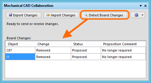
Detecting changes to the board.
Once all changes have been made, detected, and proposition comments added, those changes can be exported using the Export Changes button. This will create an EDMD Changes file (ECAD Changes n.idx).
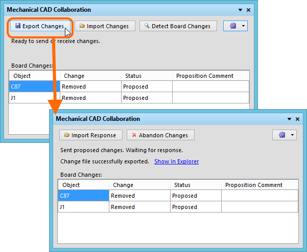
With proposed changes to the board made, export to create an EDMD Changes file, to send those proposed changes to the mechanical designer.
It is now up to the mechanical designer to import and view the change proposals on their side. They will then either accept or reject each proposed change in turn, and send back their response in an EDMD Response file (MCAD Response n.idx). Once this is received, import the response using the Import Response button. To apply the changes in the response file, simply click the Apply Changes and Respond button, thus generating an EDMD Response file from the ECAD side back to the mechanical designer (ECAD Response n.idx).
This handshaking ensures that both parties are synchronized with the changes made.
Importing Changes
If the mechanical designer is proposing changes, those changes will be proposed in an EDMD Changes file (MCAD Changes n.idx). Import the changes using the panel's Import Changes button. The changes will be listed in the Changes from Mechanical CAD region of the panel, in terms of:
- Object - for example the component designator.
- Change - for example Moved for a component that has been moved within the design.
- Status - which will be Proposed since the change is originating on the MCAD side.
- Proposition Comment - a note to explain the change to the electrical designer.
It is now up to you, as the electrical designer, to view and either accept or reject each proposed change in turn. As you click on a listed board change, a flashing highlight will be used to indicate the location of that change within the PCB document. To accept a proposed change, check its associated Accept check box. To reject, leave this unchecked. Once all proposed changes have been accepted/rejected, click the Apply Changes and Respond button. The accepted changes will be applied to the PCB document, and an EDMD Response file (ECAD Response n.idx) sent back to the mechanical designer.